

Introduction
Welcome to Popcorn Computer’s CHIP documentation.
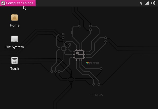
Welcome to The CHIP Operating System
We made a computer. And every computer needs an operating system.
Ours is The CHIP Operating System. Grab an old TV (or any screen with a composite video input), a keyboard and mouse, and stick some electricity in the micro USB port. In a few seconds, you’ll have CHIP’s operating system on your screen, ready to do computer things.
CHIP is built for making - we’ve packed a powerful processor, 4 GB of storage, stereo audio, video out, and lots of connections for playing and making your projects and products.
The CHIP Operating System is built for doing: browse the ‘net, send email, play video games, listen to music, write a novel, watch a video, or learn programming. And because it’s based on the popular Linux Debian, if there’s something you need, you can probably install it.
So how do use this thing? Let’s get started.
Start CHIP. Boot CHIP.
First things first. Let’s boot CHIP into the CHIP Operating System and do some computer things! Add some power, turn on the wireless network, and even connect a bluetooth keyboard to get rid of those annoying cables.
Power Up
The single most important thing to using any electronic device is getting electricity to the right places. We’re going to cover how to turn CHIP “on”. This might seem so straightforward that it doesn’t deserve several paragraphs, but CHIP is pretty clever, so there’s actually a few things worth knowing.
What’s It Need?
In general, CHIP is powered by a 5-volt source like a USB port or phone charger, and draws about 500mA peak (at boot time), runs on around 200mA, and rests with around 80mA with the processor totally unloaded. To make sure you have enough headroom, we recommend that you use a 5v power supply with 2 Amps current available (you could go as low as 900mA, but you risk brown-outs). This may be more than you need to know if you just want to plug it in to the wall, but, as you build projects with CHIP, you’ll be happy to know there’s a lot of ways to get the electricity flowing.
How Do I Know CHIP Is On?
CHIP is silent. It doesn’t take much energy, so it’s not very hot. It has no discernible smell. As a result, many of your senses are not great indicators that it is working. There are two LEDs next to the USB micro connector. When CHIP is on, you should see the PWR LED light up nice and bright.
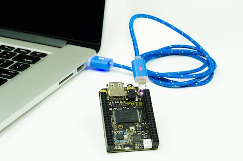
Power From The Wall
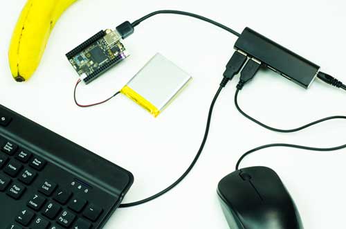
The CHIP’s microUSB connector is used to provide power from most any USB power source. USB wall-wart adapters are probably littered all over your house. If for some reason you don’t have one, you can buy one at any electronics retailer. We recommend a 5V powersupply with 2 Amps current available. Just plug a USB-A-to-microUSB-B cable (that’s the same cable most phones, tablets, and whatnot use to charge) into the wall-wart and CHIP, and you’ll see the PWR LED light up. This CHIP is using the power from a computer’s USB port:
Power From A Battery
CHIP can also be battery powered. Specifically, any single cell (1S) 3.7V Lithium Polymer (LiPo) battery with a 2-pin JST-PH 2.0mm end can be connected to the JST-PH socket.
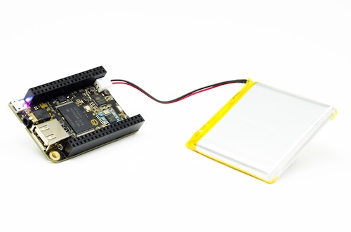
The JST can only plug it in one way: if you are having a hard time lining things up, turn it around! Needless to say, do not force the battery connector into the socket if something doesn’t feel right!
If you have added a connector to your own battery, make sure you have the JST wired correctly: the (-) connection should be on the outside edge of CHIP.
What’s really great is that if you plug in to a charger and plug in a battery, the battery will charge - all the power management is on CHIP itself. Roughly, it takes about four to six hours to charge a 3000 mAh LiPo battery from a 5V 2A power source. Also, our delightful little Power Management IC, the AXP209, handles pass-through power, so while on and charging a battery, CHIP is basically running on a un-interruped power supply – If charge power fails, CHIP seamlessly switches onto battery power without shutting off.
Now you’re ready to connect CHIP to a screen, keyboard and mouse or even work on CHIP from another computer.
Button
There is a tiny tiny button on CHIP next to pin header U13 that is used for turning CHIP on or off. If CHIP is off and connected to a power source, hold down the button for one second to power it up. To turn CHIP off (rather brutally), hold the button for 10 seconds. We recommend using the operating system to power CHIP off, but if you need to, you can use this button.
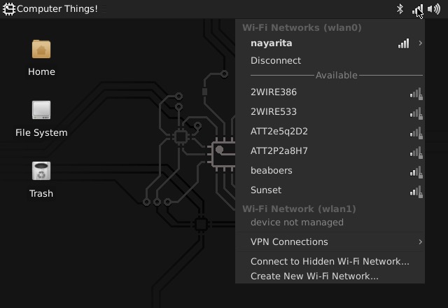
Connect To WiFi
Connecting to a WiFi network is easy using the WiFi icon the top right system tray. Just select a network to initiate a connection. If the network requires a password you’ll be prompted for it. You can also set up Wi-Fi from the command line.
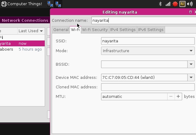
If you need more control and information over your network connection, use the Settings->Network Connections panel to show your connections. Double click on a connection to bring up the connection editor:
Connect Bluetooth
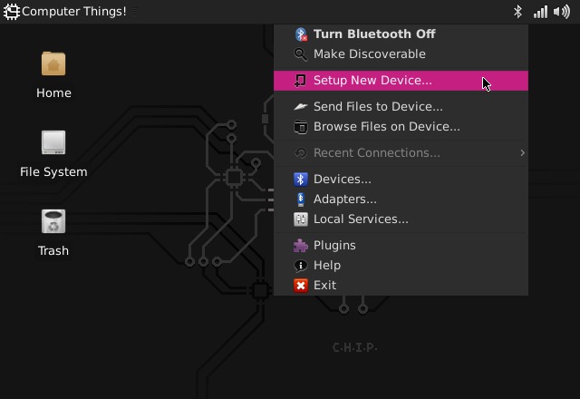
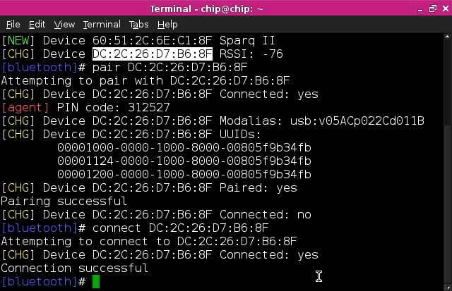
Bluetooth device setup can be accessed using the Bluetooth icon in the top right system tray.
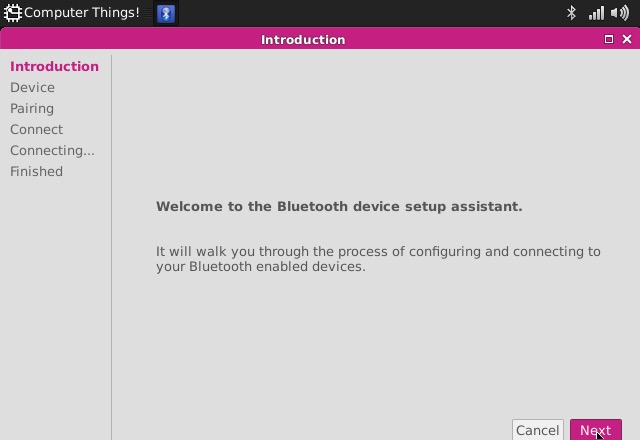
When you begin a connection, you’ll be guided through the necessary steps to connect to your device. For example, when you pair with a keyboard, you’ll often be prompted for a code to enter to ensure a unique connection. Once you have paired a device, future connections will usually be automatic when the devices are in range and powered up.
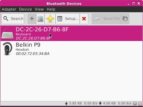
You can manage, and also connect to, your devices using the the Bluetooth Devices panel, accessed from the Bluetooth system tray:
Using The Terminal
One of the great powers of Linux is the so-called “command-line.” This simple text interface for computing unveils many of the gears and levers that make a computer tick. Many find it easier to get things done, as it is a focused and terse way to interact with the computer.
When you first use the Terminal Emulator program, you may quickly find that you do not have permission to do something. That is because many commands are safely reserved for “root” access, and you are automatically logged in as the “chip” user. Don’t fear: you can often use the sudo command and use the default password chip to execute these restricted commands.
Finally, it is probably wise to change the default password on your CHIP. You can do with with
passwd
or
sudo passwd root
and you’ll be asked for a new password. Don’t forget it!!
If you are such a fan of the command line, you may want to boot with out the desktop and window system. Instructions for that are here
Terminal for Beginners Glossary
One of the great things about Linux is the terminal application.
While it may look unfriendly and terse, if you want to really extend the capabilities of CHIP, you’ll often find yourself in the terminal.
If you’re a beginner, here’s a quick reference of some really important and common commands. You can simply add -h to get some hints on how to use a command, such as cp -h or you can read a manual page using man cp. Most unix commands have a variety of options that can be executed in the command with flags, such as ls -l -a. Even better, search the internet! This primer is simply here to help you understand what a command might be doing, not to help you use it to its full ability.
- cd change directory. open a folder. ex:
cd ~/Pictureschanges your current directory to the home Pictures folder, so you can easily access the files within. - mkdir make directory. create a folder. ex:
mkdir Vacationmakes a folder named Vacation in the current directory.mkdir ~/Pictures/Vacationmakes aVacationfolder in the home Pictures directory. - ls list files in the current directory so you know what is in it. Some options are
ls -lto list in long format to provide information about permissions, size, and date.ls -ato show hidden files that start with the.character. - mv move a file from one directory to another, or to give it a new name. Ex:
mv this.one that.onerenames a file.mv this.one ~/Pictures/Vacation/puts the file this.one into theVacationdirectory. - cp copy a file from one place to another. Ex:
cp this.one this_01.onewill copythis.oneto another filethis_01.one. Add directories for more fun:cp ~/Pictures/Vacation/saturn.jpg /Users/otherone/Pictures/Vacation/saturn.jpg. - rm remove a file. delete it, and beware!. Use the
-rto make it recursive to delete a directory. Ex:rm this.onedeletes that file.rm -r ~/Pictures/Vacationto forget the good times. - sudo super user do. many commands need administrator-like privileges, otherwise they won’t work.
apt-getis a command that needs to be run withsudoto allow files to be written to protected directories. You’ll seesudoas the first word in a lot of commands - all it is doing is giving the command the necessary access. You’ll be asked for a password the first time you usesudo. The default password and user is “chip”. - apt-get the command used for installing, removing, and finding software for Debian Linux systems, such as the CHIP Operating System.
sudo apt-get install puredatainstalls the Pure Data program and any dependencies.sudo apt-get remove puredatawill remove the program.sudo apt-cache search imagewill search apt repositories for the keyword search. And so on. - pwd present working directory. In case you forget where you are. Not much to it:
pwdwill output the directory name, such as/Users/home/chip/Pictures/Vacation/ - grep a tool used for searching through files. It’s quite deep and can be complicated, but if you see the word
grepin some command, you know it’s searching for a match. - | (pipe) a command used to redirect data into an application.
- < (redirect) a command use to redirect data into a file.
- cat and echo concactenate. append data to a file. Ex:
echo "Last line of text" >> sometext.txt. Merge files:cat append.txt >> main.txtwill put all the text in append.txt into main.txt. Overwrite:echo "New contents of text file" > whatevs.txtwill replace all text in the file with the text in quotes. Display text in file:cat showit.txtwill print the contents in the terminal window. Create:cat > new.txtwill let you create a new text file in the terminal by typing lines (ctl-c to exit). - less makes it so you can paginate and read a text tile. Ex:
less longtext.txtwill fill the screen with the first part of the longtext.txt file. Use the space bar to view the next page. Typeqto exit. - nano a text editor. You’ll often see commands that call
nanoso you can edit a configuration. Ex:nano /etc/avahi/services/afpd.serviceto edit the avahi Apple file service file. - find look for files in the filesystem. Ex:
find ~/Documents -name particular.txt -type fwill look for the file with the nameparticular.txtin the Documents directory. - chmod change mode. Used for file permissions, which can be important when sharing things on the network, scripting actions, and many more reasons.
- htop display the processes currently alive on the CPU. If things seem slow, or you want to see how much CPU or memory a program is using, just type
htopto see a table of all running processes, then typeqwhen you want to exit. - scp secure copy. copy a file from one computer to another over a network. Ex:
scp Pictures/Vacation/motel.jpg Pictures/Vacation/accident.jpg chip@otherchip.local:~/Picturescopies a couple jpegs to another computer on the network. - ssh secure shell. access another computer on the network and use the terminal commands to make changes and control it. Ex:
ssh chip@chip.localto access your CHIP on a local network. - CTRL C if you can’t use the terminal because a process is taking too long, type CTRL-C on your keyboard to cancel the most recent command.
Connecting Accessories
CHIP has a lot of connectors, some for building, some for doing normal computer things. This section covers the normal computer things, like audio, video, and input.
Recommended Accessories
CHIP is a minimal computer. Many CHIP users may never connect common peripherals, instead using CHIP as a “headless” computer. Like desktop computers from Best Buy, you may find that certain accessories will improve the overal usability of CHIP. We recommend:
- Bluetooth Keyboard
- USB mouse
- Monitor with a composite video input
- USB cable: USB-A to microUSB-B
- TRRS to RCA connector
- 2A, 5V USB power supply
Additionally, some of the advanced tutorials require:
- Speakers with RCA audio input
- Jumper wire
- USB to UART cable
- Single cell Lithium Polymer battery
Powered USB Hub
You’ll find that a simple powered USB hub is pretty essential if you want to use a lot of USB devices with CHIP. Not only is there only one USB port (keeping CHIP nice and small), but CHIP’s micro USB power port can only provide so much power for the USB port. If you don’t have a powered USB port, you’ll quickly max out power if you attach too many accessories.
Keyboard and Mouse
Many keyboards have USB hubs built-in, so you can attach a mouse to the keyboard, attach the keyboard to CHIP, and immediately have control. However, it’s likely the two will draw too much current, so you’ll want to connect to a powered hub before you connect.
Bluetooth Keyboard and Mouse
As you know, CHIP has built-in bluetooth. If you want to use a keyboard and mouse, you can keep your USB port free for other things (like mass storage or a MIDI controller!) and keep your desk clean. See connecting to bluetooth section
Monitor
In the spirit of keeping things small, CHIP packs all the audio and video into a small TRRS (Tip-Ring-Ring-Sleeve) connector. Built-in video output is restricted to standard composite video resolution of 640x480. Higher video resolutions are possible using the VGA and HMDI DIP boards.
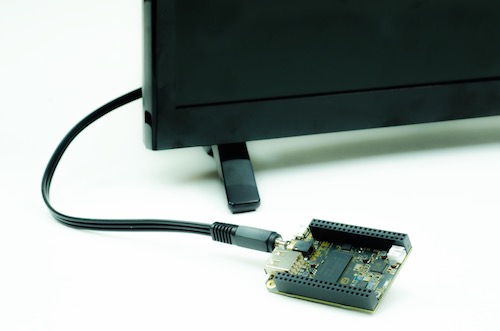
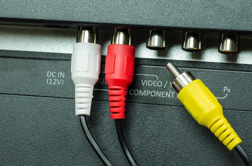
Here’s what the other end of the cable looks like, attached to a monitor with stereo audio inputs (red and white) and the composite video plug, moved so you can see the label on the monitor:
About the TRRS Connector
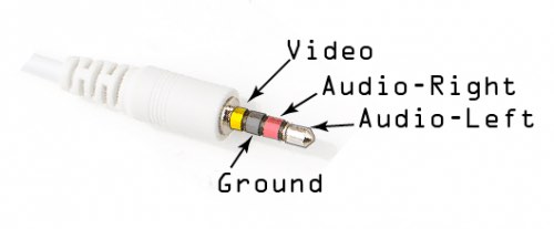
CHIP has a 1/8" (3.5mm) Tip-Ring-Ring-Sleeve (TRRS) output jack, capable of carrying stereo audio, and either composite video out, or microphone in.
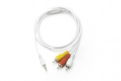
This is a fairly common port, but there are a few different arrangements of the conductors, so not all cables are equal. Fortunately, CHIP uses the same conductor arrangement as Pi, Zune, and iPod audio/video cables, so the most common “mini to RCA A/V” cables should work just fine.
Some cables will route signals a bit differently, using the Red RCA cable for Video instead of Yellow. If video out isn’t working through the yellow cable, see if red works. If not, your cable may be a version that’s arranged in a way that it just won’t work with CHIP:
- yellow : video
- red : stereo audio right channel
- white : stereo audio left channel
The conductors on the TRRS plug are arranged like this:
If you want to learn even more about TRRS connectors and the general lack of standardization with them, this page has even more details.
NTSC or PAL
The composite video format is NTSC by default. If you need to hook up to a monitor that only uses a PAL signal, you’ll need to change that at u-boot time. First, connect to CHIP with a UART cable. Then power up CHIP, and press a key on the keyboard to boot into u-boot mode to change the environment variable manually.
printenv video-mode
setenv video-mode (mode data)
saveenv
reset
where mode data can be, for NTSC and PAL respectively:
setenv video-mode sunxi:640x480-24@60,monitor=composite-ntsc,overscan_x=40,overscan_y=20

setenv video-mode sunxi:720x576-24@50,monitor=composite-pal,overscan_x=40,overscan_y=20
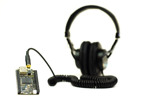
Headphones
The audio and video connector on CHIP can be dedicated to audio output suitable for headphones or connecting to an amplifier for filling a room or public space with glorious sound. Just connect a standard 3.5 mm (1/8") TRS audio plug into CHIP’s a/v jack. Of course, if headphones are plugged in, there will be no room for a composite video output jack. You can also get audio left, common, and right output from pins 4, 6 & 8 on header U14.
Microphone and Audio Input
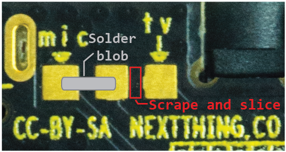
If you want to use audio input, you might find it easiest to use the pins on pins 10 and 12 on header U14. However, if you want to use the 1/8" TRRS connector, you can modify the CHIP board to replace the composite video connection with an audio input connection.
If you look at the bottom of CHIP with the audio and USB jacks pointed up, you’ll see three small contact pads to the left of the audio jack. The left pad has a small label of mic and the right pad has a tv label. Between the middle pad and the tv pad is a trace that can be carefully cut with an Exacto or utility razor blade. Once that is cut (check with a volt or continuity meter), you can put a solder blob between the mic and middle pad. Now the outer ring can be used for audio input.
As another reference, if you had X-ray vision and you were looking from the bottom of CHIP, you’d see a trace like this:
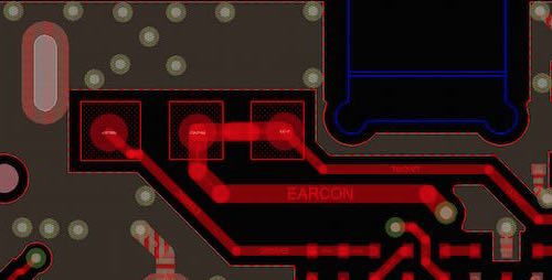
If the composite video connection is needed again, just reverse the process: desolder the connection between mic and the middle pad, then solder a bridge between tv and the middle pad.
Microphone with Header Pins
If you want to use the pins 10 and 12 on header U14, you’ll most likely need to add some additional circuitry to get a good input signal. Here is a schematic of the simple circuit:
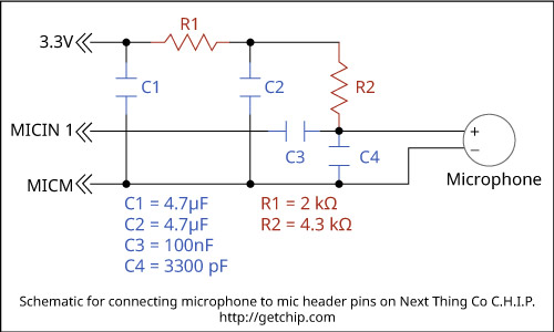
You’ll need two 4.7 microfarad capacitors, one 100 nanofarad capacitor, and a 3300 picofarad capacitor. You’ll also need one 2 kilo-ohm and one 4.3 kilo-ohm resistors.
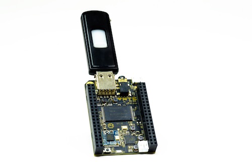
USB Storage
If you have files that you want to modify, use, or transfer to CHIP’s internal storage, you can attach a USB thumb drive, card-reader, or hard drive. Open the file manager and access the files.
USB Audio
CHIP can use Class-compliant USB audio devices. A popular, and inexpensive choice for audio devices are USB dongles based on the C-Media chipset. These have been tested successfully with CHIP and can often be purchased for less than $10. Some good resources for linux and audio compatibility are on the linux audio and alsa project websites.
Many of the drivers have not been tested with CHIP - as CHIP matures, more information will be available. For now, we recommened USB Class-compliant or “plug-and-play” audio devices.
Battery and Charging
Like any modern laptop, CHIP can run and charge any single-cell LiPo battery. Read more in the powering CHIP section.
Using The CHIP Operating System
If you’ve used a desktop or laptop computer before, the CHIP Operating System should be pretty familiar. There are menus, icons to click, menus with more stuff when you right-click, keyboard shortcuts, applications to run, and settings to set. CHIP is small, so we keep our operating system simple. Almost everything can be accessed from the Computer Things menu: settings, launching apps, and access to files. There’s also a few convenient functions in the top right system tray.
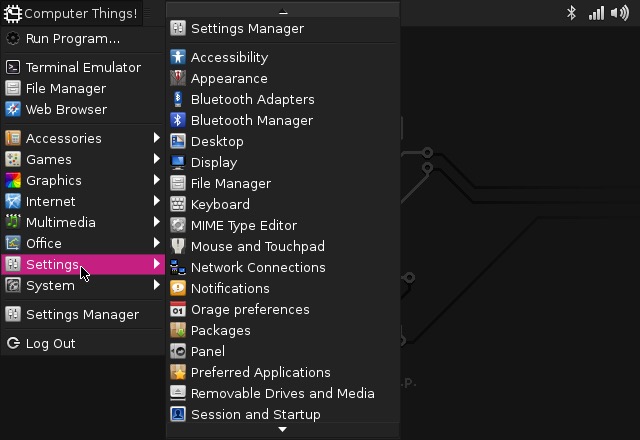
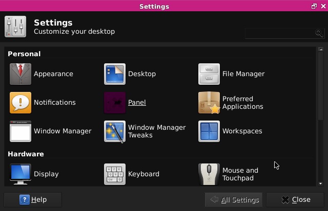
Settings and Configuration
Most of the settings for the computer and for the desktop can be set using the apps in the “Computer Things” menu. Select the appropriate app from either the Settings Menu or the Settings Manager.
WiFi
Connecting to a WiFi network is easy using the WiFi icon the top right system tray. Just select a network to initiate a connection. If you need a password, you’ll be prompted for it.
If you need more control and information over your network connection, use the Settings->Network Connections panel to show your connections. Double click on a connection to bring up the connection editor:
Bluetooth
Bluetooth device setup can be accessed using the Bluetooth icon in the top right system tray.
When you begin a connection, you’ll be guided through the necessary steps to connect to your device. For example, when you pair with a keyboard, you’ll often be prompted for a code to enter to ensure a unique connection. Once you have paired a device, future connections will usually be automatic when the devices are in range and powered up.
You can manage, and also connect to, your devices using the the Bluetooth Devices panel, accessed from the Bluetooth system tray:
Sound
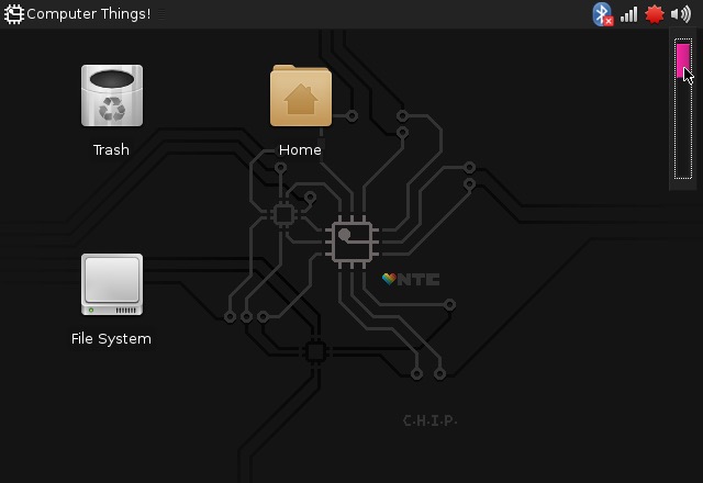
By default sound output comes from the built-in connector, served by the “sunxi codec” driver. If you want to change the volume, you can use the volume control in the top right system tray:
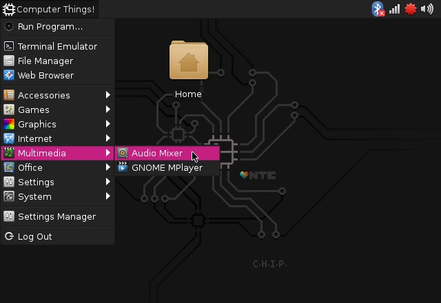
Or, open the Audio Mixer in the Multimedia category:
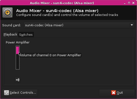
Here, you can select the “Playback” category to change the volume:
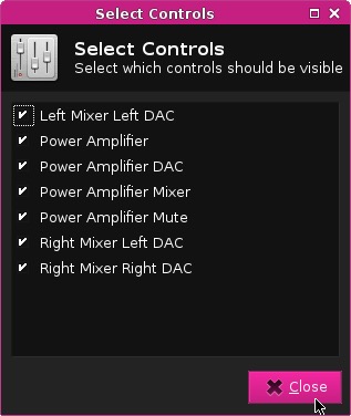
If you don’t see that control, just click on the “Select Controls” button and enable all controls:
Display
Use the Settings->Display control panel to adjust the monitor’s resolution and rotation settings:
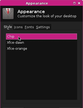
If you want to customize the desktop image, icons, colors, and fonts, there are two different panels. The Appearance panel lets you select a theme to make instant changes for several properties.
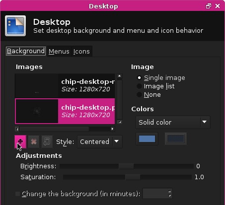
The Desktop panel lets you customize images and colors, along with the behavior of menus.
If you want to change the theme or the icon sets, you can search for these using the Synaptic Package Manager. Search for gtk2 themes or icon sets. There are also packages that can make it easy to find and configure themes, such as gtk-theme-config. Similarly you can use the command line to search packages with apt-cache search gtk2 theme.
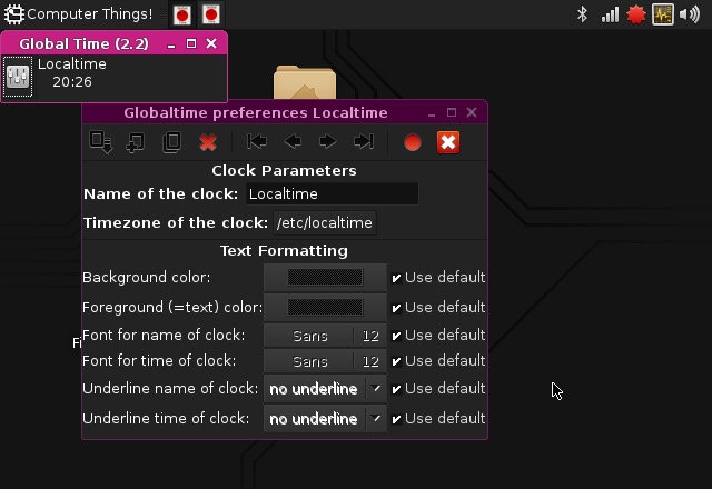
Time and Date
Set the Time with the Orage Globaltime panel. This can be found in Accessories->Orage Globaltime or in Office->Orage Globaltime. Simply click the time to bring up the preferences panel. You can quickly view the date from the Orage Calendar in the Office menu.
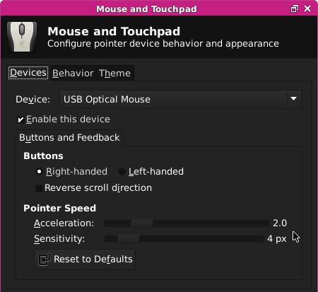
Mouse Sensitivity
Mouse sensitivity is set for the default 640x480 resolution. If you are using CHIP with a higher resolution monitor, you may want to adjust the sensitivity of the mouse. You can get to the Mouse settings panel from Computer Things->Settings->Mouse and Touchpad
Language and Location
CHIP’s operating system comes with a default language of English. You can change the language and the location, but you’ll need to use the terminal to do so. Use the “Computer Things!” menu to launch the Terminal Emulator.
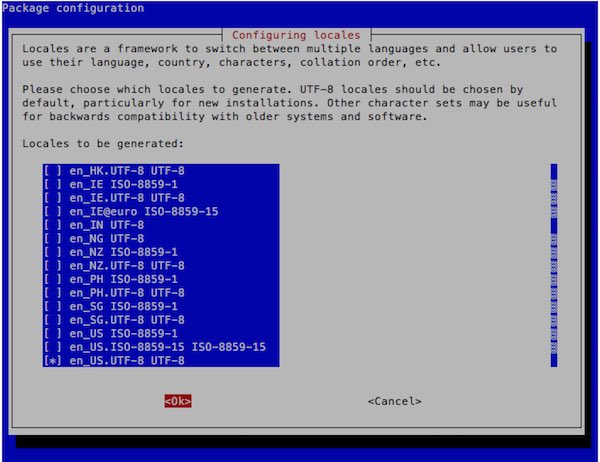
Then use the apt-get command to install the language packs and run a simple program to configure your language and location:
sudo apt-get update && sudo apt-get install locales && sudo dpkg-reconfigure locales && sudo locale-gen
You’ll get a large menu to select locales. Use the arrow keys to scroll down and spacebar to mark your location with an [*]. It’s advised that you choose the location marked UTF8. Others are somewhat arcane edge cases! Hit return to continue.
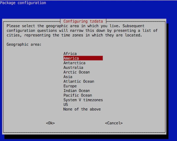
You can set the timezone with
sudo dpkg-reconfigure tzdata
Launching Installed Apps
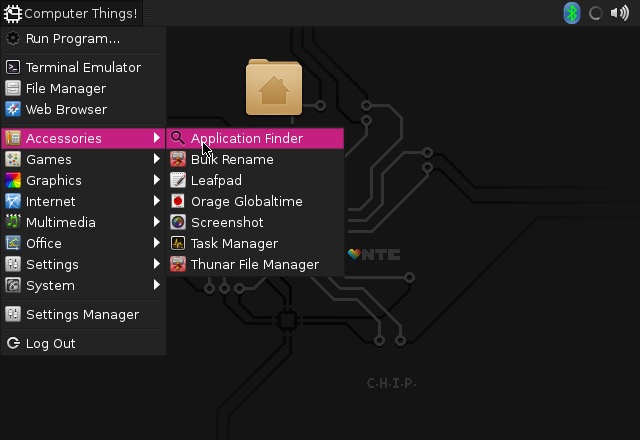
CHIP comes prepackaged with many open-source applications to get you started. It’s easy to launch an application. You can select an application from the “Computer Things!” menu and select an app from the categories:
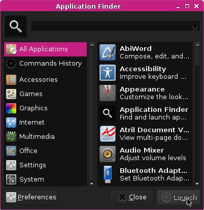
Or, for more control, launch the Application Finder in Accessories, where you can use the search bar and easily navigate among the categories:
Below are some of the applications that come pre-installed with CHIP:
AbiWord
AbiWord is a fully featured word processor. You can learn more at The AbiWord website
Web Browser
CHIP OS ships with the Ice Weasel browser. It is a Debian Linux version of the Firefox browser.
The browser is largely the same as Firefox, just with a different name.
More information is at the Debian website and in this stack exchange thread.
If you update your system (either through Synaptic or the command apt-get update && apt-get upgrade, you will suddenly find that your browser is called Firefox. This change is documented on the debian wiki

Video Player
CHIP plays video! Use the built-in Mplayer to open and play videos.

Terminal (commandline)
The life blood of linux. If there’s something you can’t do on the desktop, or you want to automate tasks, or access different hardware settings using nothing but a keyboard and text, you’ll open up Terminal.
Complete List of Installed Software
These are the applications installed by default on CHIP as accessed through the GUI.
- Application Finder
- Bulk Rename
- Leafpad
- Orage Globaltime
- Screenshot
- Task Manager
- Thuner File Manger
- Xarchiver
- Alex the Allegator 4
- Spout
- Viewnior
- Ice Weasel Web Browser
- Audio Mixer
- GNOME MPlayer
- QjackCtl
- AbiWord
- Atril Document Viewer
- Gnumetric
- Orange Calendar
- Orage Globaltime
- Htop
- Package Updater
- Synaptic Package Manager
- Xfce Terminal
- Notifications
- Various System Settings
- Zip (and UnZip)
Install and Update Software
Synaptic Package Manager
Launch the Synaptic Package Manager to find and install new software.
Synaptic is a graphical interface to the apt-get command and will install software intended for DERP and other debain-based systems. You can learn more about Synaptic here
There’s a simple search bar to make it easy to find packages you are interested in. If you don’t find the package you are looking for, hit the Reload button to refresh Synaptic’s record of available packages.
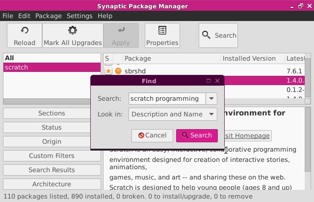
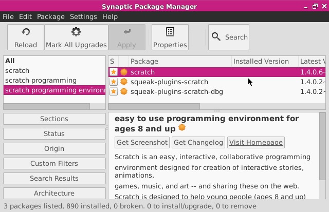
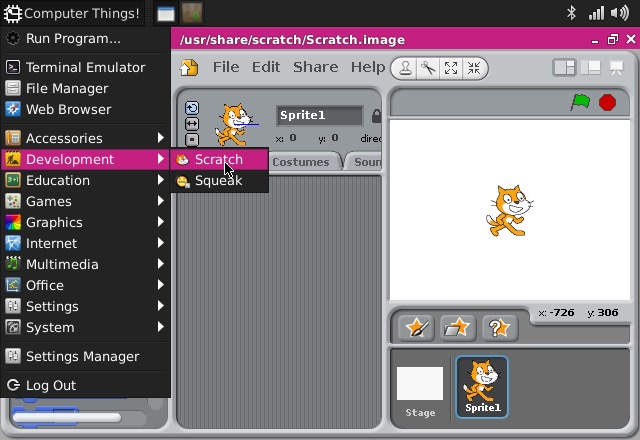
Example: Installing Scratch Programming Environment
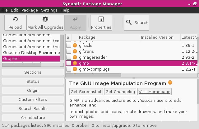
Using Synaptic is very easy. For example, if you wanted to install the Scratch Programming Environment, you can simply search for “scratch” and you’ll get a lot of results. Scroll through, and you’ll eventually find “scratch” in the packages window. However, you’ll probably want to narrow your results with better search terms, such as “scratch programming environments”
When search is complete, you can select “scratch” from the package panel.
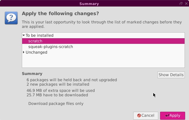
Press the top “Apply” button, and you’ll get the following dialog:
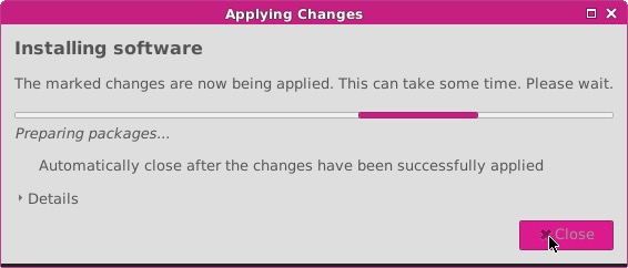
and you’ll be notified of the progress:
After a minute or so, you’ll be notified that it’s finished:
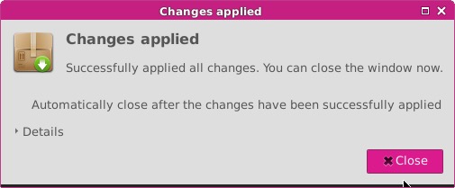
Now that it’s installed, you can launch scratch:
Auto Update
CHIP will automatically look for any updates and alert you if updates are available for your existing software and the operating system.
apt-get
If you are using the commandline, you will use apt-get to install and update new software.
If you are new to apt, some important commands to know:
sudo apt-get updateupdates the information from repositories, so any installs you make withinstallwill be the latest packagesudo apt-get upgradeupgrades any installed packages.sudo apt-get install (name of package)to install a package and any of its dependencies.sudo apt-get remove (name of package)will remove a package and any dependencies not used by other packagessudo apt-get purge (name of package)will remove a package and any dependencies not used by other packages along with all settings dataapt-cache search (search terms)will search through the package repositories for names and descriptions that include your search term.
Uninstall Software
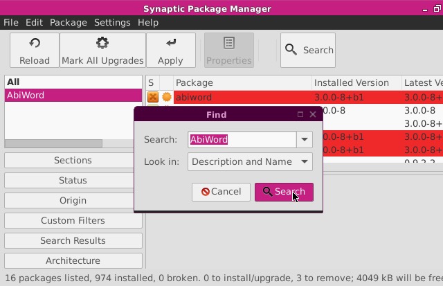
You can use the Synaptic Package manager to uninstall any packages you no longer need. If you know the name, you can use the Search function to find the package, then Mark it for Removal.
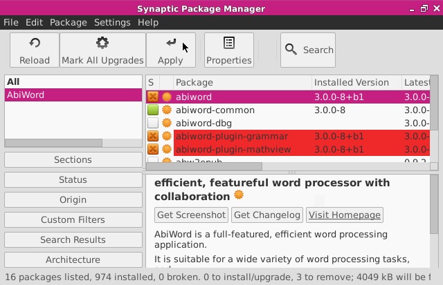
For example, if you want to remove AbiWord, first open Synaptic and search for “abiword”:
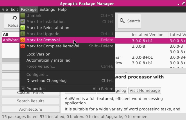
Once found, select AbiWord in the package list, and select “Mark for Removal” in the Package menu:
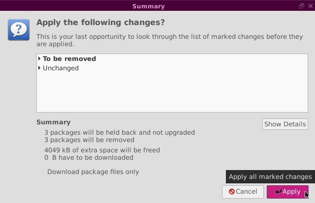
If there are additional, related packages that need to be removed, you’ll be notified:
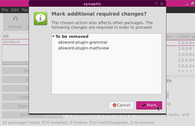
Finally, press the top “Apply” menu to remove the packages:
You’ll be notified what changes will be applied:
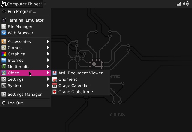
Finally, you can confirm that AbiWord has been removed by checking the Applications menu:
Boot into Console
If you want want CHIP to boot directly into a console, and not load the Desktop or Window manager GUIs, there are a couple options. For the temporary case, you can open a terminal window and use the command
sudo systemctl set-default multi-user.target
Next time you boot CHIP, it will not load the desktop or window environment, leaving you with command-line operation only. If you wanted to return to booting into the GUI, you can use this command before you reboot:
sudo systemctl set-default graphical.target
The other option is to run a linux distribution with no GUI installed. You may want to do this if you want to use commandline only and want to save some storage space. You can follow instructions to flash CHIP with buildroot, or Debian (with no GUI).
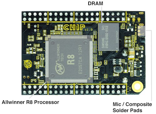
CHIP Hardware
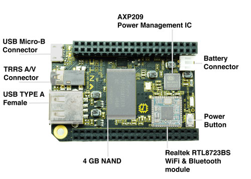
At around 30 grams, CHIP is small, but it packs a lot of hardware on the PCB. Here’s an overview of the connections and components.
Parts and Pieces
Wireless
WiFi
CHIP supports 802.11b/g/n using the built-in WiFi.
Bluetooth
CHIP supports the Bluetooth 4.0 LE standard using the built-in Bluetooth.
Physical Connectors
CHIP is loaded with essential connectors for USB, serial, audio, video, and loads of IO on the pin headers.
USB
The single USB port on CHIP is USB 2.0 compatible. It can provide up to 500mA of current, as is standard for USB ports on computers. If you need to provide more current, we recommend a powered USB hub.
USB On The Go
The micro USB port is generally used to provide power for CHIP. However, since CHIP can be powered through the pin headers or a battery, this port can be used for different things.
By default, connecting CHIP’s micro USB to a computer will create a USB Serial connection, so you can access CHIP with a screen or cu session in a terminal. With Linux kernel modifications, it is possible to enable other modes, such as an Ethernet bridge.
Composite Video and Stereo Audio
The 1/8" TRRS connector provides composite video and stereo audio output. Headphones can be plugged in for audio only.
Audio Input uses the same connection on the TRRS connector as the composite video signal. If you want to make audio input active on the TRRS connector, you need to cut a circuit board trace. This is not as permanent as it sounds, as it is easy to re-enable composite video out with a small amount of soldering.
Pin Headers
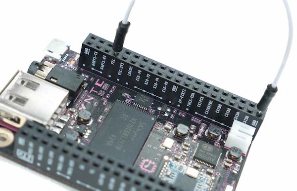
The Pin Headers provide a massive amount of connectivity, making CHIP a suitable platform for product development for physical computing and “internet of things” devices. Here’s a basic diagram that labels all the pins:
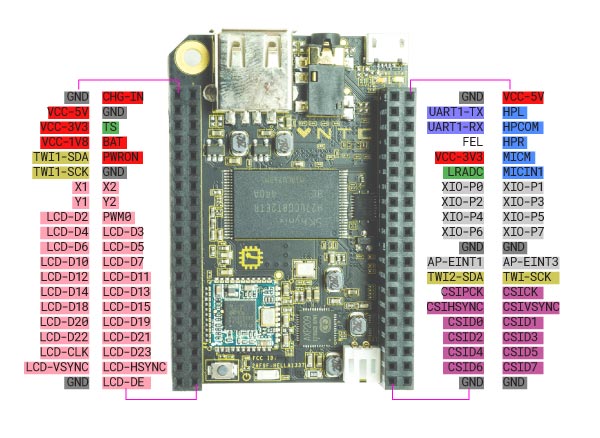
| U13L | U13R | U14L | U14R |
|---|---|---|---|
| GND : ground | CHG-IN : 5V input (power and battery charge) | GND : ground | VCC-5V : 5V power |
| VCC-5V : 5V power | GND : ground | UART1-TX : UART serial transmit | HPL : audio out left |
| VCC-3V3 : 3V power | TS : analog temperature sensor input | UART1-RX : UART serial receive | HPCOM : audio out common ground |
| VCC-1V8 : 1.8 V power | BAT : LiPo battery | FEL : “fel mode”: connect to ground to put CHIP in fel mode for firmware | HPR : audio out right |
| TWI1-SDA : two-wire serial bus 1 | PWRON : power on | VCC-3V3 : 3 volt power | MICM : mic mute |
| TWI1-SCK : two-wire serial bus 1 | GND : ground | LRADC : low-res Analog-Digital Converter | MICIN1 : audio in |
| X1 : Resistive touchpanel input (touchscreen) | X2 : Resistive touchpanel input (touchscreen) | XIO-P0 : expander GPIO | XIO-P1 : expander GPIO pin 1 |
| Y1 : Resistive touchpanel input | Y2 : Resistive touchpanel input (touchscreen) | XIO-P2 : expander GPIO pin 2 | XIO-P3 : expander GPIO pin 3 |
| LCD-D2 : RGB666 data | PWM0 : pulse width modulation (also used for LCD backlight dimming) | XIO-P4 : expander GPIO pi | XIO-P5 : expander GPIO pin 5 |
| LCD-D4 : RGB666 data | LCD-D3 : RGB666 data | XIO-P6 : expander GPIO pin 6 | XIO-P7 : expander GPIO pin 7 |
| LCD-D6 : RGB666 data | LCD-D5 : RGB666 data | GND : ground | GND : ground |
| LCD-D10 : RGB666 data | LCD-D7 : RGB666 data | AP-EINT1 : Application Processor Interrupt | AP-EINT3 : Application Processor Interrupt pin, necessary for certain kinds of hardware-software interactions (keyboard expander, etc.) |
| LCD-D12 : RGB666 data | LCD-D11 : RGB666 data | TWI2-SDA : two-wire serial bus 2 (I2C) | TWI2-SCK(*) : two-wire serial bus 2 (I2C) |
| LCD-D14 : RGB666 data | LCD-D13 : RGB666 data | CSIPCK : CMOS serial interface | CSICK : CMOS serial interface, can be used for attaching a serial camera sensor |
| LCD-D18 : RGB666 data | LCD-D15 : RGB666 data | CSIHSYNC : CMOS serial interface | CSIVSYNC : CMOS sync |
| LCD-D20 : RGB666 data | LCD-D19 : RGB666 data | CSID0 : CMOS serial interface | CSID1 : CMOS serial interface |
| LCD-D22 : RGB666 data | LCD-D21 : RGB666 data | CSID2 : CMOS serial interface | CSID3 : CMOS serial interface |
| LCD-CLK : RGB666 clock | LCD-D23 : RGB666 data | CSID4 : CMOS serial interface | CSID5 : CMOS serial interface |
| LCD-VSYNC : vertical sync for LCD screen | LCD-HSYNC : horizontal sync for LCD | CSID6 : CMOS serial interface | CSID7 : CMOS serial interface |
| GND : ground | LCD-DE : RGB666 data | GND : ground | GND : ground |
(*)The XIO GPIO pins are provided by an I2C Expander at address 0x38 on the TWI bus 2, as such, this address is not available on bus 2.
Mechanical Drawing
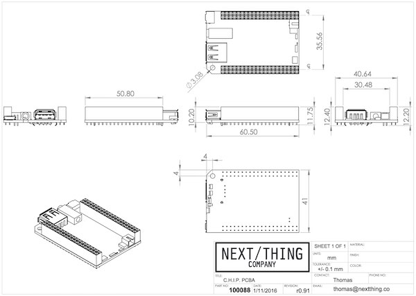
Our git repo for CHIP hardware has a mechanical drawing
Open Source Hardware: Where To Get It
CHIP is open source hardware. Here’s where you can get all the data you need to make, modify, or learn about your own CHIP. Visit the CHIP Hardware git repository.
Making Stuff
CHIP is more than a cool, small, inexpensive computer. It’s a complete system for building projects that require remote control, network connectivity, and physical interfacing with people and the environment. CHIP’s pin headers have all the connections to make this happen. An annotated diagram of the pin headers can be found in the hardware section of this manual.
GPIO
GPIO provides basic digital connections to the physical world to create physical products with CHIP. These pins can act as ‘reads’ or 'writes’, for example, to sense switch positions or turn an LED on or off.
CHIP’s most easily available IO pins are the “XIO” pins on header U14. This is the “GPIO eXpander” that uses an I2C bus to create eight (8) convenient pins for GPIO. These use address 0x38 on the TWI bus 2. Other pins are available for GPIO if more than eight are needed.
Read and Write From Command Line
CHIP has several General Purpose Input/Output (GPIO) pins available for you to build around. If you want to access them in a very primitive way, just to confirm their existence, here’s some things to try.
Requirements
- CHIP
- Jumper Wire
- LED
- SSH or serial connection to CHIP or
- Monitor and keyboard
How You See GPIO
There are eight (8) GPIO pins always available for connecting CHIP to the sense-able world. If you orient CHIP with the USB connector pointed up, you’ll find the GPIO pins in the middle of the right header, U14, Pins 13-20, labeled XIO-P0 to P7:
GPIO Library
There is an excellent library for working with GPIO and CHIP’s IO busses, made available by our wonderful community. Check out the Adafruit_Python_GPIO and the CHIP_IO libraries. These make it very easy to get started with making things with CHIP.
Kernel 4.3 vs 4.4 GPIO - How To Tell The Difference
For various reasons related to the community nature of Linux development, the GPIO expander pin numbers are different between CHIP OS kernels 4.3 and 4.4. What follows is a very technical discussion of the GPIO access. If you just want to start making stuff and don’t need low-level information, you might just want to skip this section and go straight to the python library.
If you are developing applications on CHIP that use GPIO pins and you would like consistent behavior between the kernel versions, you need to know how to find out the base value for the GPIO values. It may be enough for you to know that the GPIO expander pins start at 408 on 4.3, 1016 on 4.4.11, and 1013 on 4.4.13-ntc-mlc, however, it would be ideal to calculate this in your application to truly future-proof for future kernels.
If you look in the directory /sys/class/gpio, you’ll find two directories starting with gpio: gpiochip0 and either gpiochip408 (4.3) or gpiochip1016 (4.4.11) or gpiochip1013 (4.4.13-ntc-mlc).
The 408 or 1016 or 1013 are the bases for the expander pins. If you want to definitively find out what the base is using code, you should
cat gpiochip*/label
cat gpiochip*/ngpio
cat gpiochip*/base
The label you are interested in is the value pcf8574a which is the device that provides GPIO expansion. This provides the number of GPIO as returned by ngpio. The first expander pin starts with the base value. If you parse all these values and apply to your code, you can setup your application to be kernel-agnostic for GPIO access.
Here is a python script that demonstrates this in a gist
Here is a bash script to compute the base (courtesy of bbs user @fordsfords)
LABEL_FILE=`grep -l pcf8574a /sys/class/gpio/*/*label` BASE_FILE=`dirname $LABEL_FILE`/base
BASE=`cat $BASE_FILE`
Finally, you can view a practical example of calcualting the “xio base” in the CHIP_IO library common.c code.
How The System Sees GPIO
There is a sysfs interface available for the GPIO. This just means you can access the GPIO states in a file-system-like manner. For example, you can reference XIO-P0 using this path:
/sys/class/gpio/gpio408/
The number is somewhat unfortunate, since the sysfs names do not match the labels on our diagram! But is not too hard to translate. Pins XIO-P0 to P7 linearly map to gpio408 to gpio415 on kernel 4.3 and gpio1016 to gpio1023 on kernel 4.4.11. For kernel 4.4.13-ntc-mlc the range is gpio1013 to gpio1019. See above to learn more about that distinction.
Some GPIO Switch Action
These lines of code will let us read values on pin XIO-P7. First, we tell the system we want to listen to this pin:
    #4.3
  sudo sh -c 'echo 415 > /sys/class/gpio/export'
  #4.4.11
  sudo sh -c 'echo 1023 > /sys/class/gpio/export'
  #4.4.13-ntc-mlc
  sudo sh -c 'echo 1019 > /sys/class/gpio/export'
View the mode of the pin. It should return “in”:
    #4.3
  cat /sys/class/gpio/gpio415/direction
  #4.4.11
  cat /sys/class/gpio/gpio1023/direction
  #4.4.13-ntc-mlc
  cat /sys/class/gpio/gpio1019/direction
Connect a jumper wire between Pin 20 (XIO-P7) and Pin 39 (GND). Now use this line of code to read the value:
    #4.3
  cat /sys/class/gpio/gpio415/value
  #4.4.11
  cat /sys/class/gpio/gpio1023/value
  #4.4.13-ntc-mlc
  cat /sys/class/gpio/gpio1019/value
Some GPIO Output
You could also change the mode of a pin from “in” to “out”
    #4.3
  sudo sh -c 'echo out > /sys/class/gpio/gpio415/direction'
  #4.4.11
  sudo sh -c 'echo out > /sys/class/gpio/gpio1023/direction'
  #4.4.13-ntc-mlc
  sudo sh -c 'echo out > /sys/class/gpio/gpio1019/direction'
Now that it’s in output mode, you can write a value to the pin:
    #4.3
  sudo sh -c 'echo 1 > /sys/class/gpio/gpio415/value'
  #4.4.11
  sudo sh -c 'echo 1 > /sys/class/gpio/gpio1023/value'
  #4.4.13-ntc-mlc
  sudo sh -c 'echo 1 > /sys/class/gpio/gpio1019/value'
If you attach an LED to the pin and ground, the LED will illuminate according to your control messages.
Enough IO
When you are done experimenting, you can tell the system to stop listening to the gpio pin:
    #4.3
  sudo sh -c 'echo 415 > /sys/class/gpio/unexport'
  #4.4.11
  sudo sh -c 'echo 1023 > /sys/class/gpio/unexport'
  #4.4.13-ntc-mlc
  sudo sh -c 'echo 1019 > /sys/class/gpio/unexport'
Learn More
You can learn more about GPIO and Linux here:
Python Library
There is a well-maintained python library that works for 4.3 and 4.4 kernels available here. This is analogous to the RPi.GPIO library, but is designed for CHIP. It’s an excellent place for quickly working with GPIO and PWM on CHIP.
GPIO Types
There are many types of sensors that can be used with GPIO:
Switches
Switches provide on/off state input from the physical world to your computer. You can use the commandline interface to listen to switch values. A python library was created for the ChippyRuxpin project if you need a higher-level example in python.
LEDs
LEDs can be illuminated and turned off using the commandline interface. Refer to the ChippyRuxpin project on a good example on how to manipulate the commandline using python.
Relays
Relays are special hardware bridges used to switch higher voltage electronics, protecting CHIP from the high voltages that would destroy it. Using a relay board is programmatically no different from using switches.
Expanding GPIO
If you don’t need to drive an LCD, you can use those pins for more, faster GPIO if you want to. These are the pins numbered 18-40 on U13 and 27-40 on U14 to act as GPIO to increase the number of available GPIO pins.
Finding GPIO Pin Names
The process for reading the pins using sysfs are the same as the documentation above. You can calculate the Pin name using the Allwinner R8 Datasheet, starting on page 18.
The letter index is a multiple of 32 (where A=0), and the number is an offset. For example PD4 is LCD_D4 so
D=3
(32*3)+4 = 100
Therefore, listening to LCD_D4 in sysfs would begin with
sudo sh -c 'echo 100 > /sys/class/gpio/export'
Analog to Digital Conversion
Pin 9 on header U14 provides a link for low resolution analog to digital conversion (ADC). There is no driver for this link yet. ADC is used to read continuous sensors (temperature, pots, FSR, photoresistor, etc)
1 Wire
Only available in CHIP OS 4.4 and above, the 1 Wire serial protocol data is accessible from the sysfs device. Find your one wire devices with
ls /sys/bus/w1/devices/2*/eeprom
The * is there because your eeprom device will register a unique UUID number with C.H.I.P., so the ls command will show you all available one wire devices.
UART
UART connections can be made using the UART connections on header U14. It allows serial connection which can be used to:
- Connect from another machine to CHIP via remote serial console
- Use CHIP to connect to a microcontroller or other peripheral which has a serial interface (see below).
Serial connection to a microcontroller or other peripheral
First stop Getty to avoid most shell stdin/stdout to interfere with UART. Yes most, saddly kernel messages will still go though and there is currently no way to stop them (and they may happen from time to time after boot):
$ sudo systemctl stop serial-getty@ttyS0.service
You may even disable completely that service so that it remains off after reboot but then you won’t be able to use the serial console:
$ sudo systemctl mask serial-getty@ttyS0.service
You can then use UART as a standard serial port from /dev/ttyS0. Below is a little sample experiment to test your UART port:
Example usage
Connect UART Tx to Rx directly via a cable. So all outputs will come as inputs.
Install PySerial (we’ll have to run our process as root to get access to the port):
$ sudo pip install pyserial
Write this little script and save it for example as test.py:
    import serial
    import time
    with serial.Serial('/dev/ttyS0') as ser:
    for i in range(10):
        ser.write([i])
        print(bytearray(ser.read())[0])
        time.sleep(1)
Finally let’s run it:
    $ sudo python test.py
    1
    2
    3
    ...
    99
PWM
Pulse Width Modulation can be used to control
motors and other devices. It is possible to use GPIO pins to drive motors, but they generally are
not fast enough for robust and smooth control. PWM can be accessed through an sysfs protocol.
I2C
I2C (Inter-Integrated Circuit) can be accessed through
a sysfs protocol using the debian i2c-tools. In the terminal, use
sudo apt-get install i2c-tools
Note that the “XIO GPIO” pins are provided by an I2C expander at address 0x38 on the TWI bus 2, so that address cannot be used on bus 2.
LCD Monitor Support
Using the numerous LCD header pins, a color touchscreen panel can be directly implemented on CHIP.
Project Examples
Projects coming soon!
Flash CHIP With an OS
You might want (or need) to completely re-flash your CHIP with a different operating system. We’ve made it really easy to do this by embedding the entire process in a browser-based application. Just hook CHIP up to your computer, fire up a browser, and flash your CHIP
Things you will need
- C.H.I.P.
- Standard-USB to micro-USB connector
- Thin Paper clip (a jumper wire works too)
- Separate computer with Chrome or Chromium browser
Instructions
If you don’t have the Google Chrome or the open-source Chromium browser on your other computer, install it by following the preceding links.
Ok, good. Now that you have installed the browser, you can visit flash.getchip.com in Chrome or Chromium and follow all the instructions. If you are using a computer with USB3 ports, it’s suggested that you attach a USB2-compliant hub and connect your CHIP to the hub, instead of directly to the USB3 port.
It’s possible to run the entire operation online. There are also options for downloading the OS image to your computer’s harddrive, then flashing your CHIP with no additional need for internet access.
FEL mode
Here is a photo (which may be clearer than the animation in the web flasher) which shows where to place your jumper wire or paper clip:
Note: this jumper needs to be present only when you connect CHIP to power. If for some reason the wire becomes disconnected after you have powered CHIP, there is no problem or need to panic.
For more information on OS-specific issues, see here.
The SDK Way
You may not want to use the browser-based flashing procedure. If this is the case, or you need additional tools, you can flash using the CHIP SDK
Web Flasher OS-Specific Issues
Before you try anything else, try using a different USB cable. Many cables are charging-only, or do not support high bandwidth and will cause flashing to fail.
Windows-specific
- You must install drivers to be able to talk with C.H.I.P.
- Reboot after installing drivers on previous versions (<10) of Windows.
Unfortunately, due to the nature of how Windows manages drivers, the flashing procedure will likely fail the first time you use it. When that happens, try completely closing and reopening your browser. Depending on your version of windows, this might happen twice, once when waiting for FEL, and then again waiting for Fastboot.
Troubleshooting The Web Flasher
- Try using a USB2 port (USB3 ports have issues).
- Try passing through a USB2 hub if using a USB3 port.
- Try a different USB cable. They often are bad.
- Try turning off antivirus software.
- If you get stuck “Waiting for Fastboot” and the above options don’t work, you should be able to install a “headless no fastboot” image. However, it will take quite a bit longer, and the Operating System won’t have a GUI.
MacOS specific
- There are some times where using USB3 ports will cause the flashing to fail. If you can, try using a USB2 port, not a USB3. Recent Macs have only USB3 ports. If you find yourself with a modern Mac, try using a USB2 hub in your USB3 port and plug C.H.I.P. into that.
- If you get stuck “Waiting for Fastboot” and the above options don’t work, you should be able to install a “headless no fastboot” image. However, it will take quite a bit longer, and the Operating System won’t have a GUI.
- OS X El Capitan has been known to have issue with the flashing process. If a new cable or USB2 hub does not work and you are able to, upgrade to macOS Sierra.
Linux-specific
Linux requires permissions to write to C.H.I.P. when its plugged into your computer. Chrome (or Chromium) does not have these permissions, so you need to explicitly create them before you’ll be able to use the web flasher .
On Ubuntu:
You need to paste the following into a terminal:
sudo usermod -a -G dialout ${USER}
sudo usermod -a -G plugdev ${USER}

# Create udev rules
echo -e 'SUBSYSTEM=="usb", ATTRS{idVendor}=="1f3a", ATTRS{idProduct}=="efe8", GROUP="plugdev", MODE="0660" SYMLINK+="usb-chip"
SUBSYSTEM=="usb", ATTRS{idVendor}=="18d1", ATTRS{idProduct}=="1010", GROUP="plugdev", MODE="0660" SYMLINK+="usb-chip-fastboot"
SUBSYSTEM=="usb", ATTRS{idVendor}=="1f3a", ATTRS{idProduct}=="1010", GROUP="plugdev", MODE="0660" SYMLINK+="usb-chip-fastboot"
SUBSYSTEM=="usb", ATTRS{idVendor}=="067b", ATTRS{idProduct}=="2303", GROUP="plugdev", MODE="0660" SYMLINK+="usb-serial-adapter"
' | sudo tee /etc/udev/rules.d/99-allwinner.rules
sudo udevadm control --reload-rules
Then logout and log back in.
For the curious:
- ${USER}: outputs your username
- dialout: gives non-root access to serial connections
- plugdev: allows non-root mounting with pmount
The udev rules then map the usb device to the groups.
For more information, check the systems group page on debian.org.
USB3 Issues * If you have any issues, try using a USB2 port and not a USB3 one, or try using a USB2 hub in your USB3 port and plug C.H.I.P. into that. * If you get stuck “Waiting for Fastboot” and the above options do not work, you should be able to install a “headless no fastboot” image. However, it will take quite a bit longer, and the Operating System won’t have a GUI.
Caveat In rare cases, you may have an issue with your computer putting C.H.I.P. into auto-suspend mode. Here is an example on how to fix this problem:
apt-get install laptop-mode-tools
#### edit /etc/laptop-mode/conf.d/runtime-pm.conf, uncomment/change AUTOSUSPEND_RUNTIME_DEVID_BLACKLIST
#### add all fel devices to the blacklist:
AUTOSUSPEND_RUNTIME_DEVID_BLACKLIST="1f3a:efe8"
reboot
Advanced
For those interested in building with a stripped-down version of an operating system, or looking to customize CHIP from the command line, we have several tutorials that describe how to setup CHIP with more depth.
Installing C.H.I.P. SDK
CHIP-SDK has everything needed to develop software for C.H.I.P. Most importantly, if you want to load an operating system onto CHIP, the only supported way is to do this from a virtual machine. Given that the virtual machine runs Ubuntu, it’s pretty safe to say that Ubuntu users can flash without the virtual machine.
Requirements
- Computer running OS X 10.10+, Ubuntu 14.04+, or Windows 7+
- At least 1 GB free RAM, up to 40 GB of disk space may be used
- Software: VirtualBox, Vagrant, git, terminal
Software Setup
There are several required software pieces to get the CHIP SDK virtual machine running.
Install VirtualBox and Extensions
- Get the installer for Virtual Box
- Install the Oracle VM VirtualBox Extension Pack.
- If you are using Windows, you need to add the VirtualBox installation directory to your PATH.
- In case of an Ubuntu host: add your user to the vboxusers group!
Install Vagrant
Install Vagrant from the Vagrant site. Alternatively, if OS X, you can use the homebrew package manager: brew install caskroom/cask/brew-cask brew cask install vagrant
Install Git
Installation of Git depends on your operating system:
- Windows: direct to download
- Debian Linux:
sudo apt-get install git - OS X homebrew:
brew install git
Clone the CHIP-SDK repository and boot the Virtual Machine
Assuming you have git in your PATH, open up a terminal and type:
git clone https://github.com/NextThingCo/CHIP-SDK
and start up the virtual machine:
cd CHIP-SDK
vagrant up
Login To Virtual Machine
In the same shell on the host type the following:
vagrant ssh
If everything went well you should see the following prompt:
vagrant@vagrant-ubuntu-trusty-32:~$
All The Commands At Once
Here’s all the commands in one place:
git clone https://github.com/NextThingCo/CHIP-SDK
cd CHIP-SDK
vagrant up
vagrant ssh
Congratulations! Now you’re ready to Flash a C.H.I.P. from your SDK!
Troubleshooting Flashing from the SDK
Here are a few possible problems.
Shared Folder Out of Sync
In case you run into trouble because the kernel in the VM was updated and the shared vagrant folder can no longer be mounted, update the guest additions by typing the following in the CHIP-SDK directory on the host:
vagrant plugin install vagrant-vbguest
This blog post has some more tips on keeping additions in sync.
Invalid State
If you get an error like:
error: The guest machine entered an invalid state while waiting for it to boot.
This probably means your version of VirtualBox needs updating and/or needs the Extension Pack. Update as necessary and try vagrant up again.
Couldn’t Find File
If you get the error:
error: Couldn't open file /Volumes/Satellite/gitbins/CHIP-SDK/base
that means you didn’t cd CHIP-SDK. Very basic, perhaps, but late nights sometimes need that bump!
Updating the CHIP-SDK Virtual Machine
You may have been working with CHIP for a while now, and you want to updated your SDK. It’s only slightly more involved than sync'ing with the git repo; you have to update the virtual machine, too.
Requirements
- Computer running OS X 10.10+, Ubuntu 14.04+, or Windows 7+
- Existing installation of CHIP-SDK
How To Update
Just follow these steps:
On your host operating system, pull the latest changes from our Git repository:
  cd ~/CHIP-SDK
  git pull
Make sure the virtual machine is shut down and update it:
  vagrant halt
  vagrant provision
Now you can boot the virtual machine and ssh into it:
  vagrant up
  vagrant ssh
Once you see the trusty prompt, your CHIP SDK virtual machine is ready to use:
vagrant@vagrant-ubuntu-trusty-32:~$
All The Commands At Once
Here’s all the commands in one place:
  cd ~/CHIP-SDK
  git pull
  vagrant halt
  vagrant provision
  vagrant up
  vagrant ssh
Flash CHIP Firmware
Now that the virtual machine and SDK are running and configured, you can connect CHIP to your computer and give it an operating system. If you want to flash using a native Ubuntu installation, read how to prepare Ubuntu to flash
Prepare CHIP for Flashing
Prepare CHIP with a jumper wire connecting Pin 7 and Pin 39 on header U14 (FEL pin and GND). Here’s a reference image that labels the headers and pins:
Note: this jumper needs to be present only when you connect CHIP to power. If for some reason the wire becomes disconnected after you have powered CHIP, there is no problem or need to panic.
Now connect CHIP to your computer with a micro-USB->USB-A cable. The power LED will illuminate.
Option 1: Flash With NTC Buildroot OS
Buildroot is a lean operating system, and does not have a package manager to install software. You can add additional software before you flash CHIP by customizing buildroot.
  cd ~/CHIP-tools
  ./chip-update-firmware.sh -f
The -f option means “fastboot.” If you have problems flashing, particularly on Windows or OS X, you can run ./chip-update-firmware.sh to disable fastboot flashing.
During flashing, the terminal will fill with messages. If successful, you’ll see C.H.I.P. run through a hardware test, with the answers being ‘OK’. If C.H.I.P. is 'OK’, you can remove the jumper wire. Here is a sample successful output.
Option 2: Flash With Debian
If you want to flash CHIP with the debian OS with no window manager or GUI
  cd ~/CHIP-tools
  ./chip-update-firmware.sh -d -f
The -f option means “fastboot.” If you have problems flashing, particularly on Windows or OS X, you can disable fastboot by leaving off the -f option: ./chip-update-firmware.sh -d. Here is a sample successful output.
Option 3: Flash With CHIP Operating System
If you want to flash CHIP with the complete CHIP Operating System with a desktop manager and GUI:
  cd ~/CHIP-tools
  ./chip-update-firmware.sh -d -b stable-gui -f
During flashing, the terminal will fill with messages. If successful, you’ll see C.H.I.P. run through a hardware test, with the answers being 'OK’. If C.H.I.P. is 'OK’, you can remove the jumper wire. Here is a sample successful output. Because of filesize, the “gui” option must also include the -f fastboot option. Windows and OS X are not yet supported as flashing hosts.
Connect to CHIP and Do Something
If everything went OK, you can now power up your CHIP again and connect via serial as a USB gadget:
screen /dev/ttyACM0 115200
You can login to CHIP as chip or root using the password chip.
and even test the hardware:
sudo hwtest
Customize Buildroot
Buildroot is a tool for building and cross-compiling a linux distribution that only has what you need. Setting up buildroot requires either a virtual machine or a computer running Ubuntu OS, setup for flashing.
Modify and Build
C.H.I.P.-buildroot is used to build buildroot and the linux kernel. Its Makefile operates on a .config file which specifies options to include in the build. The .config lives in the repository’s root, whereas the one for the linux kernel is: ./board/chip/linux.config/
First, clone the buildroot repot and create the default config file with:
git clone https://github.com/NextThingCo/CHIP-buildroot
cd CHIP-buildroot
make chip_defconfig
This will copy the the chippro_defconfig file as .config in the root of the repository. Other default config targets for other hardware can be found in the config subdirectory. You can, of course, create your own config files and use them later.
Customize the buildroot using
make nconfig
For Linux (which will modify the linux.config under board/nextthing/chip/):
make linux-nconfig
Now
make
from the buildroot repository root. This will cross-compile linux/buildroot for C.H.I.P. Pro. The targets wind up in the ./output/images directory. If you make changes to your config files, you can just make again without a make clean.
This will take a while, maybe an hour. When finished, flash CHIP with the script:
  cd ~/CHIP-tools
  BUILDROOT_OUTPUT_DIR=../CHIP-buildroot/output ./chip-fel-flash.sh
Unless you changed the users or passwords, you can login to CHIP as chip or root using the password chip.
Buildroot Cheat Sheet
Here’s a very terse explanation of how the make commands work in CHIP-buildroot:
CHIP-buildroot/
├── make chip_defconfig
│   ├── apply pre-existing chip-specific configuration to buildroot
│   └── apply pre-existing chip-specific configuration to kernel
├── make chippro_defconfig
│   ├── apply pre-existing chippro-specific configuration to buildroot
│   └── apply pre-existing chippro-specific configuration to kernel
├── make linux-nconfig
│   └── make realtime changes to currently applied kernel defconfig
└── make nconfig
    └── make realtime changes to currently applied buildroot defconfig
The defconfig is a sort of macro that loads a suggested starting point for a buildroot OS, for packages (nconfig) and kernel (linux-nconfig).
Use make nconfig to add packages for extending the capabilities, like you might with a package manager in debian.
The make linux_nconfig command modifies the kernel for specific drivers or hardware additions.
Appendix
Sample outputs are provided in this appendix so you can more easily troubleshoot or proceed with confidence when flashing CHIP with firmware.
Buildroot Output
Sample output from flashing Buildroot to CHIP looks like:
ROOTFS_URL=http://opensource.nextthing.co.s3.amazonaws.com/chip/buildroot/stable/71/images
BUILD=71
BR_URL=http://opensource.nextthing.co.s3.amazonaws.com/chip/buildroot/stable/71/images
BR_BUILD=71
/home/doge/gits/CHIP-tools/.firmware/images/rootfs.ubi exists... comparing to http://opensource.nextthing.co.s3.amazonaws.com/chip/buildroot/stable/71/images/rootfs.ubi
MD5: 90315ca1fb8ff95fc6878ce8126bdf02
S3_MD5: 6d59af4a0f673e1d61147e4a06dd7ba8
md5sum differs
--2015-10-21 15:59:16--  http://opensource.nextthing.co.s3.amazonaws.com/chip/buildroot/stable/71/images/rootfs.ubi
Resolving opensource.nextthing.co.s3.amazonaws.com (opensource.nextthing.co.s3.amazonaws.com)... 54.231.176.13
Connecting to opensource.nextthing.co.s3.amazonaws.com (opensource.nextthing.co.s3.amazonaws.com)|54.231.176.13|:80... connected.
HTTP request sent, awaiting response... 200 OK
Length: 54525952 (52M) [binary/octet-stream]
Saving to: ‘/home/doge/gits/CHIP-tools/.firmware/images/rootfs.ubi’

100%[======================================>] 54,525,952  1.83MB/s   in 29s

2015-10-21 15:59:45 (1.82 MB/s) - ‘/home/doge/gits/CHIP-tools/.firmware/images/rootfs.ubi’ saved [54525952/54525952]

/home/doge/gits/CHIP-tools/.firmware/images/sun5i-r8-chip.dtb exists... comparing to http://opensource.nextthing.co.s3.amazonaws.com/chip/buildroot/stable/71/images/sun5i-r8-chip.dtb
MD5: de0beb674eeb382901251febfbf1cf9b
S3_MD5: de0beb674eeb382901251febfbf1cf9b
file already downloaded
/home/doge/gits/CHIP-tools/.firmware/images/sunxi-spl.bin exists... comparing to http://opensource.nextthing.co.s3.amazonaws.com/chip/buildroot/stable/71/images/sunxi-spl.bin
MD5: dd3f9c9c0984a6c1d7cdca2921f6f448
S3_MD5: dd3f9c9c0984a6c1d7cdca2921f6f448
file already downloaded
/home/doge/gits/CHIP-tools/.firmware/images/uboot-env.bin exists... comparing to http://opensource.nextthing.co.s3.amazonaws.com/chip/buildroot/stable/71/images/uboot-env.bin
MD5: 6f2b79a781f9f490911012ec3aa653e9
S3_MD5: 6f2b79a781f9f490911012ec3aa653e9
file already downloaded
/home/doge/gits/CHIP-tools/.firmware/images/zImage exists... comparing to http://opensource.nextthing.co.s3.amazonaws.com/chip/buildroot/stable/71/images/zImage
MD5: 0d35ad764564a2cee9281715823597a2
S3_MD5: 0d35ad764564a2cee9281715823597a2
file already downloaded
/home/doge/gits/CHIP-tools/.firmware/images/u-boot-dtb.bin exists... comparing to http://opensource.nextthing.co.s3.amazonaws.com/chip/buildroot/stable/71/images/u-boot-dtb.bin
MD5: 97340d221bcbcc8f0bf27e26adc26f0a
S3_MD5: 97340d221bcbcc8f0bf27e26adc26f0a
file already downloaded
BUILDROOT_OUTPUT_DIR = /home/doge/gits/CHIP-tools/.firmware
== preparing images ==
/home/doge/gits/CHIP-tools/spl-image-builder -d -r 3 -u 4096 -o 1664 -p 16384 -c 1024 -s 64 /home/doge/gits/CHIP-tools/.firmware/images/sunxi-spl.bin /tmp/chipflashqVYEIs/sunxi-padded-spl
filesize= 3573504
PADDED_SPL_SIZE=0x000000c6
35+1 records in
36+0 records out
589824 bytes (590 kB) copied, 0.00082507 s, 715 MB/s
12+0 records in
12+0 records out
196608 bytes (197 kB) copied, 0.0176519 s, 11.1 MB/s
Image Name:   flash CHIP
Created:      Wed Oct 21 15:59:46 2015
Image Type:   ARM Linux Script (uncompressed)
Data Size:    736 Bytes = 0.72 kB = 0.00 MB
Load Address: 00000000
Entry Point:  00000000
Contents:
   Image 0: 728 Bytes = 0.71 kB = 0.00 MB
== upload the SPL to SRAM and execute it ==
waiting for fel...OK
== upload spl ==
== upload u-boot ==
== upload u-boot script ==
== upload ubi ==
100% [============================================================]
== execute the main u-boot binary ==
== write ubi ==
flashing................OK
login... OK
password... OK
poweroff... OK
Debian Output
Sample output from a successful Debian output:
debian selected
ROOTFS_URL=http://opensource.nextthing.co.s3.amazonaws.com/chip/debian/stable/37
BUILD=37
BR_URL=http://opensource.nextthing.co/chip/buildroot/stable/71/images
BR_BUILD=71
/home/doge/gits/CHIP-tools/.firmware/images/rootfs.ubi exists... comparing to http://opensource.nextthing.co.s3.amazonaws.com/chip/debian/stable/37/rootfs.ubi
MD5: 6d59af4a0f673e1d61147e4a06dd7ba8
S3_MD5: 90315ca1fb8ff95fc6878ce8126bdf02
md5sum differs
--2015-10-21 16:06:36--  http://opensource.nextthing.co.s3.amazonaws.com/chip/debian/stable/37/rootfs.ubi
Resolving opensource.nextthing.co.s3.amazonaws.com (opensource.nextthing.co.s3.amazonaws.com)... 54.231.160.10
Connecting to opensource.nextthing.co.s3.amazonaws.com (opensource.nextthing.co.s3.amazonaws.com)|54.231.160.10|:80... connected.
HTTP request sent, awaiting response... 200 OK
Length: 245366784 (234M) [binary/octet-stream]
Saving to: ‘/home/doge/gits/CHIP-tools/.firmware/images/rootfs.ubi’

100%[======================================>] 245,366,784 1.27MB/s   in 2m 11s

2015-10-21 16:08:48 (1.78 MB/s) - ‘/home/doge/gits/CHIP-tools/.firmware/images/rootfs.ubi’ saved [245366784/245366784]

/home/doge/gits/CHIP-tools/.firmware/images/sun5i-r8-chip.dtb exists... comparing to http://opensource.nextthing.co/chip/buildroot/stable/71/images/sun5i-r8-chip.dtb
MD5: de0beb674eeb382901251febfbf1cf9b
S3_MD5: de0beb674eeb382901251febfbf1cf9b
file already downloaded
/home/doge/gits/CHIP-tools/.firmware/images/sunxi-spl.bin exists... comparing to http://opensource.nextthing.co/chip/buildroot/stable/71/images/sunxi-spl.bin
MD5: dd3f9c9c0984a6c1d7cdca2921f6f448
S3_MD5: dd3f9c9c0984a6c1d7cdca2921f6f448
file already downloaded
/home/doge/gits/CHIP-tools/.firmware/images/uboot-env.bin exists... comparing to http://opensource.nextthing.co/chip/buildroot/stable/71/images/uboot-env.bin
MD5: 6f2b79a781f9f490911012ec3aa653e9
S3_MD5: 6f2b79a781f9f490911012ec3aa653e9
file already downloaded
/home/doge/gits/CHIP-tools/.firmware/images/zImage exists... comparing to http://opensource.nextthing.co/chip/buildroot/stable/71/images/zImage
MD5: 0d35ad764564a2cee9281715823597a2
S3_MD5: 0d35ad764564a2cee9281715823597a2
file already downloaded
/home/doge/gits/CHIP-tools/.firmware/images/u-boot-dtb.bin exists... comparing to http://opensource.nextthing.co/chip/buildroot/stable/71/images/u-boot-dtb.bin
MD5: 97340d221bcbcc8f0bf27e26adc26f0a
S3_MD5: 97340d221bcbcc8f0bf27e26adc26f0a
file already downloaded
BUILDROOT_OUTPUT_DIR = /home/doge/gits/CHIP-tools/.firmware
== preparing images ==
/home/doge/gits/CHIP-tools/spl-image-builder -d -r 3 -u 4096 -o 1664 -p 16384 -c 1024 -s 64 /home/doge/gits/CHIP-tools/.firmware/images/sunxi-spl.bin /tmp/chipflashUooSfo/sunxi-padded-spl
filesize= 3573504
PADDED_SPL_SIZE=0x000000c6
35+1 records in
36+0 records out
589824 bytes (590 kB) copied, 0.00181383 s, 325 MB/s
12+0 records in
12+0 records out
196608 bytes (197 kB) copied, 0.0164913 s, 11.9 MB/s
Image Name:   flash CHIP
Created:      Wed Oct 21 16:08:49 2015
Image Type:   ARM Linux Script (uncompressed)
Data Size:    736 Bytes = 0.72 kB = 0.00 MB
Load Address: 00000000
Entry Point:  00000000
Contents:
   Image 0: 728 Bytes = 0.71 kB = 0.00 MB
== upload the SPL to SRAM and execute it ==
waiting for fel...OK
== upload spl ==
== upload u-boot ==
== upload u-boot script ==
== upload ubi ==
100% [============================================================]
== execute the main u-boot binary ==
== write ubi ==
flashing...........................OK
login... OK
password... OK
poweroff... OK
Failure
There are a couple common errors that occur when flashing.
The first is a that CHIP is not in fel mode, ready to receive firmware. There are three possible reasons for this:
- You already successfully flashed CHIP, and haven’t disconnected the USB cable from your computer.
- The jumper wire between Pins 7 & 39 is either not present, loose, or the jumper is in the wrong holes.
- There is a problem with the USB cable.
You’ll know this is the problem when you see this error in the terminal window:
== upload the SPL to SRAM and execute it ==
ERROR: Allwinner USB FEL device not found!
== upload images ==
ERROR: Allwinner USB FEL device not found!
ERROR: Allwinner USB FEL device not found!
ERROR: Allwinner USB FEL device not found!
ERROR: Allwinner USB FEL device not found!
== execute the main u-boot binary ==
ERROR: Allwinner USB FEL device not found!
The other common error is that you need to run the chip-update-firmware.sh script with sudo (or you need to add a rules file as described in the next section). This error looks like this in your terminal window:
Image 0: 848 Bytes = 0.83 kB = 0.00 MB
== upload the SPL to SRAM and execute it ==
ERROR: You don't have permission to access Allwinner USB FEL device
== upload images ==
ERROR: You don't have permission to access Allwinner USB FEL device
ERROR: You don't have permission to access Allwinner USB FEL device
ERROR: You don't have permission to access Allwinner USB FEL device
ERROR: You don't have permission to access Allwinner USB FEL device
== execute the main u-boot binary ==
ERROR: You don't have permission to access Allwinner USB FEL device
Option: Flash Without sudo
As a developer, there’s a good chance you’ll flash CHIP more than once in your life. You’ll probably want to follow these steps. In order to be able to run the chip-update-firmware.sh script without sudo, make a rules file:
sudo touch /etc/udev/rules.d/99-allwinner.rules
and add the content with the tee command:
echo 'SUBSYSTEM=="usb", ATTRS{idVendor}=="1f3a", ATTRS{idProduct}=="efe8", GROUP="plugdev", MODE="0660" SYMLINK+="usb-chip"' | sudo tee /etc/udev/rules.d/99-allwinner.rules
then, to make this rules file work:
shell
  sudo udevadm control --reload-rules
Setup Ubuntu For Flashing
If you are running Ubuntu OS on your computer, and don’t want to bother with a virtual machine, you can flash CHIP from your real computer. A generous member of our forums created a script that duplicates the below steps in a convenient package. You can get it from github. Please note that this is not supported or maintained by Next Thing - we only link to it here for your potential convenience.
Requirements
- Computer running Ubuntu 14.04+
- Jumper wire
- CHIP
Install Dependencies
Install some tools:
sudo apt-get update
sudo apt-get install u-boot-tools android-tools-fastboot git build-essential curl android-tools-fsutils libusb-1.0-0-dev pkg-config
If you get an error that “the repository android-tools-fastboot can’t be found”, you are probably booting from an Ubuntu Live CD (or USB stick). You’ll need to add a repository so you can install the android-tools-fastboot:
sudo add-apt-repository universe && sudo apt-get update
sudo apt-get install u-boot-tools android-tools-fastboot git build-essential curl android-tools-fsutils libusb-1.0-0-dev pkg-config
If you intend to customize buildroot with additional software, install these packages:
sudo apt-get install libncurses5-dev libc6-i386 lib32stdc++6 lib32z1
Get and make the fel tools:
git clone http://github.com/NextThingCo/sunxi-tools
cd sunxi-tools
make
sudo rm -f /usr/local/bin/fel
sudo ln -s $PWD/fel /usr/local/bin/fel
Clone the CHIP-tools repository
cd ..
git clone http://github.com/NextThingCo/CHIP-tools
cd CHIP-tools
If you have already cloned the CHIP-tools from a previous CHIP flashing, you can, of course, just update your existing repository
cd CHIP-tools
git pull
You’ll also need to add your user to some groups and add a udev rule
sudo usermod -a -G dialout $USER &&
sudo usermod -a -G plugdev $USER &&
echo -e 'SUBSYSTEM=="usb", ATTRS{idVendor}=="1f3a", ATTRS{idProduct}=="efe8", GROUP="plugdev", MODE="0660" SYMLINK+="usb-chip"
SUBSYSTEM=="usb", ATTRS{idVendor}=="18d1", ATTRS{idProduct}=="1010", GROUP="plugdev", MODE="0660" SYMLINK+="usb-chip-fastboot"
SUBSYSTEM=="usb", ATTRS{idVendor}=="1f3a", ATTRS{idProduct}=="1010", GROUP="plugdev", MODE="0660" SYMLINK+="usb-chip-fastboot"
SUBSYSTEM=="usb", ATTRS{idVendor}=="067b", ATTRS{idProduct}=="2303", GROUP="plugdev", MODE="0660" SYMLINK+="usb-serial-adapter"
' | sudo tee /etc/udev/rules.d/99-allwinner.rules
Now you are ready to flash CHIP with firmware.
Note, if you are using openSUSE, you have to change the GROUP to 'lp’.
All The Commands At Once
Here’s all the commands in one place:
sudo apt-get update
sudo apt-get install u-boot-tools android-tools-fastboot git build-essential libusb-1.0-0-dev libncurses5-dev libc6-i386 lib32stdc++6 lib32z1 android-tools-fsutils
git clone http://github.com/NextThingCo/sunxi-tools
cd sunxi-tools
make
sudo rm -f /usr/local/bin/fel
sudo ln -s $PWD/fel /usr/local/bin/fel
cd ..
git clone http://github.com/NextThingCo/CHIP-tools
cd CHIP-tools
WiFi Connection
Below are detailed instructions for connecting to Wi-Fi networks using two different command line protocols: nmcli and connman. If you are using the CHIP OS that comes installed on CHIP, or you have flashed with our Debian distribution, you’ll want to use the first section about connecting with nmcli. If you have flashed CHIP with our buildroot OS, you’ll need to use connman.
Connecting C.H.I.P. to Wi-Fi with nmcli
There are several tools in Linux for connecting and configuring networks. We will be using the command nmcli (Network Manager Client). You may see other tutorials that reference iw or iwconfig, however, these tools are not recommended for C.H.I.P. You can read more about nmcli on the internet.
Requirements
You will need one of these scenarios:
- CHIP with monitor and keyboard attached
- SSH or serial connection
- Wireless access to internet
- CHIP loaded with CHIP OS or Debian
Step 1: List available Wi-Fi networks
In the terminal, type
nmcli device wifi list
The output will list available access points
*  SSID      MODE   CHAN  RATE       SIGNAL  BARS  SECURITY
*  NextThing HQ    Infra  11    54 Mbit/s  100     ▂▄▆█  --
   NextThing Shop  Infra  6     54 Mbit/s  30      ▂___  WPA1 WPA2
   2WIRE533        Infra  10    54 Mbit/s  44      ▂▄__  WPA1 WPA2
Step 2: Connect to a network
You can connect to password -protected or open access points.
A: No Password
To connect to an open network with no password, use this command:
sudo nmcli device wifi connect '(your wifi network name/SSID)' ifname wlan0
These commands will respond with information about the connection.
B: Password Protected
To connect to a password protected network, use this command, inserting your own network name and password:
sudo nmcli device wifi connect '(your wifi network name/SSID)' password '(your wifi password)' ifname wlan0
C: Hidden SSID and Password Protected
To connect to a hidden network, append hidden yes to the command, after ifname wlan0
Step 3: Test your Connection
You can verify and test your wireless network connection.
Verify
You can verify your connection using the command
nmcli device status
which outputs a list of the various network devices and their connections. For example, a successful connection would look like this:
DEVICE   TYPE      STATE         CONNECTION
wlan0    wifi      connected     NextThing HQ
wlan1    wifi      disconnected  --
ip6tnl0  ip6tnl    unmanaged     --
lo       loopback  unmanaged     --
sit0     sit       unmanaged     --
Because it is worth knowing that Linux offers many ways of doing things, another command that shows your current active connection is
nmcli connection show --active
which outputs like so:
NAME  UUID                                  TYPE             DEVICE
NTC   59962bac-3441-437b-94ea-bf31dee66e8f  802-11-wireless  wlan0
After you have connected once, your C.H.I.P. will automatically connect to this network next time you reboot (or start NetworkManager services).
Test
Finally, you can test your connection to the internet with ping. Google’s DNS server at the IP address 8.8.8.8 is probably the most reliable computer on the internet, so:
ping -c 4 8.8.8.8
results in output like:
64 bytes from 8.8.8.8: icmp_seq=1 ttl=55 time=297 ms
64 bytes from 8.8.8.8: icmp_seq=2 ttl=55 time=26.3 ms
64 bytes from 8.8.8.8: icmp_seq=3 ttl=55 time=24.8 ms
64 bytes from 8.8.8.8: icmp_seq=4 ttl=55 time=55.7 ms
You can stop this command by pressing CTRL-C on your keyboard. The -c 4 option means it will happen only 4 times.
Congratulations! You are now network with CHIP!
Step 4: Disconnecting and Forgetting Networks
The command to disconnect from a wireless device needs a few parameters:
sudo nmcli dev disconnect wlan0
You may want to prevent auto-connection to a network, so you can use this process to “forget” a network. First, get the connection names:
nmcli c
which outputs something like
NAME       UUID                                  TYPE             DEVICE
NTC 2461   d0a6fb32-3ed8-4a95-a631-ee2ae6153761  802-11-wireless  wlan0
then, disconnect (using the example above)
sudo nmcli connection delete id "NTC 2461"
Troubleshooting Networks
Here are a few possible problems with connections.
No network found
Not much to say about that. If there’s no network, you can’t connect. Go find a network!
Incorrect password
If you type in the wrong password, you’ll get some errors like this:
[32258.690000] RTL871X: rtw_set_802_11_connect(wlan0) fw_state=0x00000008
[32258.800000] RTL871X: start auth
[32263.720000] RTL871X: rtw_set_802_11_connect(wlan0) fw_state=0x00000008
[32263.820000] RTL871X: start auth
[32264.430000] RTL871X: auth success, start assoc
[32269.850000] RTL871X: rtw_set_802_11_connect(wlan0) fw_state=0x00000008
[32269.970000] RTL871X: start auth
Error: Timeout 90 sec expired.
Try connecting again with the correct password.
Failed ping
If you don’t have access to the internet, your ping to an outside IP will fail. It is possible that you can connect to a wireless network, but have no access to the internet, so you’d see a connection when you request device status, but have a failed ping. This indicates a problem or restriction with the router or the access point, not a problem with the CHIP.
A failed ping looks something like:
From 192.168.2.56 icmp_seq=14 Destination Host Unreachable
From 192.168.2.56 icmp_seq=15 Destination Host Unreachable
From 192.168.2.56 icmp_seq=16 Destination Host Unreachable
18 packets transmitted, 0 received, +9 errors, 100% packet loss, time 17013ms
pipe 4
Loss of wireless network
A sudden, unplanned disconnection will post an error in the terminal window, for example:
[30863.880000] RTL871X: linked_status_chk(wlan0) disconnect or roaming
The Network Manager will periodically try to reconnect. If the access point is restored, you’ll get something like this in your terminal window:
[31798.970000] RTL871X: rtw_set_802_11_connect(wlan0)
[31799.030000] RTL871X: start auth
[31799.040000] RTL871X: auth success, start assoc
[31799.050000] RTL871X: rtw_cfg80211_indicate_connect(wlan0) BSS not found !!
[31799.060000] RTL871X: assoc success
nmcli not installed error
If you try to use nmcli and you get an error that it is not found or is not a command, chances are that you are using the CHIP buildroot image. The nmcli commands only apply to CHIPs running CHIP OS or Debian linux.
Connecting C.H.I.P. to a Wireless Network With connman
The buildroot operating system uses the connman command-line network manager to connect and manage your network connections. If you are using CHIP OS (or Debian), you will find that connman is not installed - you’ll need to use nmcli.
If you want all the details of connman visit the ArchLinux wiki.
Requirements
- CHIP running buildroot OS
- One of the following:
- Keyboard and monitor for CHIP
- Serial connection to CHIP
Step 1: Enable WiFi and Find a Network
These three commands will, in turn, enable wifi, scan for access points, and see what networks are available:
  connmanctl enable wifi
  connmanctl scan wifi
  connmanctl services
The services command has output similar to:
*AO
    NTC                  wifi_7cc70905cd77_4e5443_managed_psk
                         wifi_7cc70905cd77_hidden_managed_psk
    NTC Guest            wifi_7cc70905cd77_4e5443204775657374_managed_psk
                         wifi_7cc70905cd77_hidden_managed_none
    ATT312               wifi_7cc70905cd77_415454333132_managed_psk
    HP-Print-99-LaserJet 1102 wifi_7cc70905cd77_48502d5072696e742d39392d4c617365724a65742031313032_managed_none
    ATT344               wifi_7cc70905cd77_415454333434_managed_psk
    CBCI-1B57-2.4        wifi_7cc70905cd77_434243492d314235372d322e34_managed_psk
    mi-fi                wifi_7cc70905cd77_6d692d6669_managed_none
    0024A5D8CF33         wifi_7cc70905cd77_303032344135443843463333_managed_psk
    Twirl-Eco-Events-2.4 wifi_7cc70905cd77_547769726c2d45636f2d4576656e74732d322e34_managed_psk
    xfinitywifi          wifi_7cc70905cd77_7866696e69747977696669_managed_none
Step 2: Connect To An Access Point
Unfortunately, connman doesn’t use the nice name on the left of the services list. It wants the unfriendly string on the right, so you’ll want to get copy and paste ready.
A: No Password
For example, to connect to NTC Guest, which has no password, services shows two choices. We want the one without “hidden” in the string. Use the connect command to connect:
connmanctl connect wifi_7cc70905cd77_4e5443204775657374_managed_psk
If your network is not password protected, you’ll get some output that will indicate a successful connection, such as:
[  961.780000] RTL871X: rtw_set_802_11_connect(wlan0)  fw_state=0x00000008
[  962.070000] RTL871X: start auth
[  962.080000] RTL871X: auth success, start assoc
[  962.090000] RTL871X: rtw_cfg80211_indicate_connect(wlan0) BSS not found !!
[  962.100000] RTL871X: assoc success
[  962.110000] RTL871X: send eapol packet
[  962.290000] RTL871X: send eapol packet
[  962.300000] RTL871X: set pairwise key camid:4, addr:0a:18:d6:97:2d:26, kid:0, type:AES
[  962.320000] RTL871X: set group key camid:5, addr:0a:18:d6:97:2d:26, kid:1, type:AES
If your network is password protected, you’ll get an error.
B: Password-Protected
To deal with passwords, you’ll need to put connman into interactive mode:
connmanctl
which gives a connmanctl prompt:
connmanctl>
In the shell, turn the 'agent’ on so it can process password requests:
agent on
and now use the connect command (your network name will be different than what’s below of course)
connect wifi_7cc70905cd77_4e5443_managed_psk
and enter your password when prompted:
  Agent RequestInput wifi_7cc70905cd77_4e5443_managed_psk
  Passphrase = [ Type=psk, Requirement=mandatory ]
  Passphrase?
Now that you are connected to a wireless network, you can exit connmanctl interactive mode by typing
quit
All The Commands In One Place
Here’s all the commands in one place:
  connmanctl
  agent on
  connect wifi_7cc70905cd77_4e5443_managed_psk
  quit
Step 3: Test Connection
In CHIP’s command line, you can ping Google four times:
ping -c 4 8.8.8.8
and expect ping to output some timing messages like:
PING 8.8.8.8 (8.8.8.8): 56 data bytes
64 bytes from 8.8.8.8: seq=0 ttl=55 time=209.147 ms
64 bytes from 8.8.8.8: seq=1 ttl=55 time=111.125 ms
64 bytes from 8.8.8.8: seq=2 ttl=55 time=183.627 ms
64 bytes from 8.8.8.8: seq=3 ttl=55 time=147.398 ms
--- 8.8.8.8 ping statistics ---
4 packets transmitted, 4 packets received, 0% packet loss
round-trip min/avg/max = 111.125/162.824/209.147 ms
If your connection is not successful, then ping will tell you your network is down:
PING 8.8.8.8 (8.8.8.8): 56 data bytes
ping: sendto: Network is unreachable
Troubleshooting Connection Problems
- You’ll need to make sure you used the right network when you used the connect commnand.
- Review any messages that the connect commnand gave you. Did they look like the examples of a successful connection?
- If everything checked out until you got to
ping, there’s a good chance the problem is with your router or connection to the internet.
connman not installed error
If you try to use connman and you get an error that it is not found or is not a command, chances are that you are using the CHIP OS or Debian image. The connman commands only apply to CHIPs running the simple buildroot OS.
Step 4: Disconnecting And Forgetting Networks
To disconnect from your network, you might first want a reminder of what unfriendly string is used to describe your access point, so type:
connmanctl services
which will output information about your current link:
*AO NTC wifi_7cc70905cd77_4e5443_managed_psk
Use the ID to disconnect:
connmanctl disconnect wifi_7cc70905cd77_4e5443_managed_psk
and you’ll get some status like this:
[  301.890000] RTL871X: clear key for addr:0a:18:d6:97:2d:26, camid:4
[  301.900000] RTL871X: clear key for addr:0a:18:d6:97:2d:26, camid:5
[  301.920000] IPv6: ADDRCONF(NETDEV_UP): wlan0: link is not ready
Disconnected wifi_7cc70905cd77_4e5443_managed_psk
Generally, conman will remember and cache setup information - if you reboot in the vicinity of a known network, it will attempt to connect. However, if you need to forget a network setup, these setups can be found by navigating:
cd /var/lib/connman/
You can delete a single connection by seeing what connections are stored
ls /var/lib/connman/
and then delete a setup that you find, for example
rm -r wifi_7cc70905cd77_4e5443_managed_psk
You can delete all the “wifi” directories with
rm -r wifi*
(the -r is needed because these are directories you are deleting, and the star at the end of wifi* assumes your configurations all start with the string “wifi”)
For Advanced Users
It’s worth noting that you’ll see two wireless networking interfaces if you list them with
ifconfig
connman is configured to see only the physical interface wlan0 which simplifies setup. We do this with a blacklist, which can be modified at /etc/connman/main.conf
Configure Sound Output on Debian
Getting simple audio playback working on CHIP is pretty easy, once you install the correct packages and enable audio output. In the code examples below, we’ve inserted the && characters at the end of lines so you can copy and paste the entire block into a terminal window and execute each line in series. If you are using CHIP OS, sound output is already configured and working. However, you may be running a simple version of Debian or buildroot, so these instructions will help you get sound working on CHIP.
Requirements
- CHIP
- SSH or serial connection to CHIP or
- Monitor and keyboard
- Headphones or powered speakers connected to CHIP a/v jack
- Connection to a network
Setup CHIP
Update your apt repository list if you haven’t done so recently:
sudo apt-get update
Then install ALSA:
sudo apt-get install libasound2 alsa-utils
This will install alsa and some utilities for playing sound from the command line. Once those have installed, you’ll need to make the outputs active for sound
alsamixer
will open up a simple interface. Use the left and right arrow keys on your keyboard to select among the items, and use the up/down keys to change the options:
- DAC Output - set to Direct
- Left Mixer - set to Left
- PA - set to desired volume
- Right Mixer - set to Right
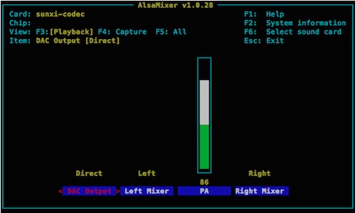
Play a Sound
Change to the root media directory:
cd /media
Alternatively, you could download a sound into chip’s home directory:
mkdir /home/chip/Media && cd /home/chip/Media
Use wget to download a sound of piano chords to the file test.wav:
wget -O test.wav https://upload.wikimedia.org/wikipedia/commons/d/db/Descending_thirds.wav
If wget returns command not found you can install it:
sudo apt-get install wget
We can finally play the sound and hear it over CHIP’s headphone jack:
aplay test.wav
If you want to play mp3 or ogg files, you can install mplayer:
sudo apt-get install mplayer
Then try an ogg file:
  wget -O test.ogg https://upload.wikimedia.org/wikipedia/commons/e/e7/Agogo.ogg &&
  mplayer test.ogg
And mp3 file:
  wget -O test.mp3 http://www.freesound.org/data/previews/315/315618_2050105-lq.mp3 &&
  mplayer test.mp3
Record A Sound
If you want to try the audio input, you need to connect audio input to header U14, pins 06 & 12 or modify CHIP to use audio in on the TRRS connector.
Once you have an audio signal going into CHIP, you can test it out by recording a three second (-d 3) WAV file with arecord:
arecord -f cd -d 3 -D hw:0,0 chipaudioin.wav
More Packages
Developers that want to use sound will probably want to download these packages:
sudo apt-get install portaudio19-dev &&
sudo apt-get install swig &&
sudo apt-get install python-setup-tools &&
sudo apt-get install python-dev
USB Storage Devices
In this tutorial, we’ll describe how you can use the USB port to add more storage with a thumb drive, hard drive, card reader, or whatever else. You can then copy, store, and edit files on the storage device, extending the capability of CHIP.
This tutorial is suitable for the buildroot image. If you are following this for other Linux distributions, there are some adjustments that you’ll need to make for paths, permissions, and enabling 'sudo.’ With buildroot, you work as the root user, so this tutorial is appropriately terse.
Requirements
- USB thumb drive or hard drive
- Computer running OS X 10.10+, Ubuntu 14.04+, or Windows 7+ (to format USB device, if needed)
Step 1: Format the Drive
First, you’ll want to format the drive as an MS-DOS (FAT), NTFS, or ext3 volume. You can do this on another computer.
Once formatted, insert the drive into CHIP’s USB port. Enter the command
dmesg
You’ll get output like:
[ 4953.430000] usb 1-1: new high-speed USB device number 2 using ehci-platform
[ 4953.580000] usb-storage 1-1:1.0: USB Mass Storage device detected
[ 4953.590000] scsi host0: usb-storage 1-1:1.0
[ 4954.590000] scsi 0:0:0:0: Direct-Access USB Flash Memory 1.00 PQ: 0 ANSI: 2
[ 4954.600000] sd 0:0:0:0: [sda] 3911616 512-byte logical blocks: (2.00 GB/1.86 GiB)
[ 4954.610000] sd 0:0:0:0: [sda] Write Protect is off
[ 4954.620000] sd 0:0:0:0: [sda] Mode Sense: 65 44 09 30
[ 4954.630000] sd 0:0:0:0: [sda] No Caching mode page found
[ 4954.630000] sd 0:0:0:0: [sda] Assuming drive cache: write through
[ 4954.650000] sda: sda1
[ 4954.650000] sd 0:0:0:0: [sda] Attached SCSI removable disk
Notice the second to last line. This tells you the device location for the drive. Storage devices generally have device names that start with “sd”. If you want to see all the storage devices attached to CHIP, you can use a wildcard to display all devices that start with “sd”:
ls /dev/sd*
and you’ll get something like:
/dev/sda /dev/sda1
With one thumb drive attached, it appears as two devices: the device itself (sda), and the storage partitions (sda1). There is only one partition on this drive.
Another way to find storage devices is the command
blkid
which lists them, along with the names you might have initialized them with:
/dev/sda1: LABEL="TEST" UUID="6668-11E9"
Step 2: Mount the Drive Device to Your Filesystem
Now that you know where your partition is, it’s time to mount the partition so you can access the files.
First, make a directory where your drive can mount:
sudo mkdir /drives
Mount the drive device to your /drives directory:
sudo mount /dev/sda1 /drives
Now you can navigate to the drives directory and see all the files in the drive:
cd /drives
ls
Step 3: Unmount the Drive From Filesystem
If you want to remove the drive from the USB port on CHIP, it’s best to unmount it:
sudo umount /dev/sda1
Step 4: Automatic Mounting on Boot
You’ll probably want to mount this drive automatically next time you use it, though. We can set that up with a quick modification to the fstab (file system table) document:
vi /etc/fstab
Getting around vi is not very intuitive. If you are new to it, here’s a quick guide on getting this text into the fstab document:
- 'arrow’ key to the end of the file,
- press the 'i’ key to insert text
- type (or copy-paste) this:
/dev/sda1 /drives vfat defaults 0 0
To exit vi,
- press the 'esc’ key,
- type ’:’ (colon),
- type 'wq’ to write and quit vi.
You can test your work with:
mount -a
If there’s an error, double check the fstab file and make sure it has the line /dev/sda1 /drives vfat defaults 0 0 at the end. If it’s successful, you’ll be able to view, modify and copy the files on the disk:
ls /drives
Now, if you reboot , the drive will mount automatically. If you remove the drive, then insert it again, you’ll need the command
mount -a
Connecting Bluetooth Devices
CHIP has built-in Bluetooth and uses the bluez 5 stack for implementing connections and devices. This tutorial instructs how to use a Bluetooth keyboard, since it is a simple and obvious example. There are, of course, several types of Bluetooth devices, such as earpieces, audio connectors, vacuum cleaners, and more. Future tutorials (search our bbs will cover those devices, but the keyboard is a good introduction to the commands and an easy way to test your system.
Requirements
- CHIP
- SSH or serial connection to CHIP or
- Monitor and keyboard
- Bluetooth device, preferably keyboard
Important!
Start with a CHIP completely unplugged and powered down. Add power and boot up. A known limitation is that after reboot, CHIP’s Bluetooth controller may not work until you power and physically disconnect from a power source.
About bluetoothctl
We’ll be using the command bluetoothctl to find, pair with, and connect to devices.
In the terminal, type
bluetoothctl
This starts up bluetoothctl in interactive mode. You should see output like
[NEW] Controller 7C:C7:08:05:CD:77 BlueZ 5.27 [default]
[NEW] Device 60:33:4B:13:A7:45 nyb
[NEW] Device 15:03:26:A0:26:26 SK032B02-2626
which is a list of MAC addresses of CHIP’s Bluetooth controller chip (the first line) and any other devices that have been paired with CHIP in the past.
Use the help command - it lists all the very useful commands in the bluetoothctl interactive mode.
In Bluetooth interactive mode, use the command
power on
which outputs
Changing power on succeeded
[CHG] Controller 7C:C7:08:05:CD:77 Powered: yes
Find A Bluetooth Device
If you need to discover a device, start the scan process:
scan on
which will start printing MAC addresses and names (if available) of Bluetooth devices in your vicinity.
[NEW] Device 15:03:26:A0:26:26 SK032B02-2626
[NEW] Device 1C:1A:C0:85:5E:2C 1C-1A-C0-85-5E-2C
[NEW] Device 60:33:4B:13:A7:45 nyb
Pair With A Bluetooth Device
Pair to a device with the MAC address and the pair command:
pair 1C:1A:C0:85:5E:2C
This may fail if the device is powered off, goes out of range, or your toddler spills water on it. Here’s what failure looks like:
Attempting to pair with 1C:1A:C0:85:5E:2C
[CHG] Device 1C:1A:C0:85:5E:2C Connected: yes
[CHG] Device 1C:1A:C0:85:5E:2C Connected: no
Failed to pair: org.bluez.Error.AuthenticationCanceled
As the scan continues, you’ll eventually see the device you are interested in, so copy that MAC address and type:
pair 15:03:26:A0:26:26
with output like:
[CHG] Device 15:03:26:A0:26:26 Connected: yes
[CHG] Device 15:03:26:A0:26:26 Modalias: usb:v05ACp3232d0001
[CHG] Device 15:03:26:A0:26:26 UUIDs:
 00001124-0000-1000-8000-00805f9b34fb
 00001200-0000-1000-8000-00805f9b34fb
[CHG] Device 15:03:26:A0:26:26 Paired: yes
Pairing successful
[CHG] Device 15:03:26:A0:26:26 Connected: no
Pair with a Bluetooth Device with Password (keyboard)
Some Bluetooth devices need user input to pair. In that case, you’ll need to turn the agent 'on’ so the device can post a password, and you can enter it:
agent on
will output
Agent registered
now you can pair it:
pair DC:2C:26:D7:B6:8F
will output
Attempting to pair with DC:2C:26:D7:B6:8F
[CHG] Device DC:2C:26:D7:B6:8F Connected: yes
[agent] PIN code: 245261
Now you can use the Bluetooth device to enter the PIN code, then hit enter. The terminal will give some status about the pairing:
[CHG] Device DC:2C:26:D7:B6:8F Modalias: usb:v05ACp022Cd011B
[CHG] Device DC:2C:26:D7:B6:8F UUIDs:
        00001000-0000-1000-8000-00805f9b34fb
        00001124-0000-1000-8000-00805f9b34fb
        00001200-0000-1000-8000-00805f9b34fb
[CHG] Device DC:2C:26:D7:B6:8F Paired: yes
Pairing successful
[CHG] Device DC:2C:26:D7:B6:8F Connected: no
Now that you are paired, you will have to connect.
Connect With A Bluetooth Device
Now that you have paired the Bluetooth device, you won’t have to do that again. However, the device still needs to be connected:
connect 15:03:26:A0:26:26
will output, when successful:
Attempting to connect to 15:03:26:A0:26:26
[CHG] Device 15:03:26:A0:26:26 Connected: yes
Connection successful
[bluetooth]## [ 1405.340000] hid-generic 0005:05AC:3232.0001: unknown main item tag 0x0
[ 1405.360000] input: SK032B02-2626 as /devices/platform/soc@01c00000/1c28c00.serial/tty/ttyS1/hci0/hci0:4/0005:05AC:3232.0001/input/input1
[ 1405.380000] hid-generic 0005:05AC:3232.0001: input: BLUETOOTH HID v0.01 Mouse [SK032B02-2626] on 7c:c7:08:05:cd:77
or, if the device is not available, it will fail:
Attempting to connect to 15:03:26:A0:26:26
[bluetooth]## [ 1304.470000] Bluetooth: HIDP (Human Interface Emulation) ver 1.2
[ 1304.480000] Bluetooth: HIDP socket layer initialized
Failed to connect: org.bluez.Error.Failed
Trusting a Bluetooth Device
Trust between people leads to understanding and perhaps even harmonious living. Trust between bluetooth devices means that you won’t have to connect the device every time it’s near. Which is a sort of harmony, I suppose. Once you have connected a bluetooth device to CHIP, if you intend to use it again, you can trust it:
trust 15:03:26:A0:26:26
Remove a Bluetooth device
You may want CHIP to not pair or connect to a device - perhaps the conveniently trusted device needs to be freed for another connection. Whatever the reason, if you want to remove your Bluetooth device,
remove 15:03:26:A0:26:26
Troubleshooting Bluetooth
If your Bluetooth controller module on CHIP is not functioning, you can easily find the problem. Type
bluetoothctl
to get into the interactive mode, then type
power on
If you get the response
No default controller available
Then there’s a problem with CHIP recognizing the Bluetooth module. Read the very first instructions at the top of this tutorial.
Install X-windows
If you want a windowed desktop on C.H.I.P., you can install X-Windows.
Requirements
- CHIP connected to WiFi
- Monitor attached to CHIP
- Keyboard or Serial or SSH Connection to CHIP
Installation (xfce4)
CHIP is a lightweight computer, so we’ll install the lightweight xfce4:
sudo apt-get install xfce4
It might take some time to download and install all the packages, since there are a lot of dependencies and libraries involved. Once installed, start the windowing system with the command
startx&
(the & runs Xwindows in the background, so you can still use your terminal). After a minute or so, you’ll get an image on the monitor:
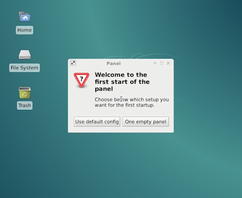
Now you can use a mouse and keyboard to explore CHIP and launch programs.
Troubleshooting apt-get
If you get errors from apt that report “unmet dependencies,” you can run the command
sudo apt-get install -f
which will force installation of any alternate or missing dependencies of any installed packages.
Install the latest PureData
The latest versions of PureData can be installed via apt-get. Use these commands (or put them in a script). This adds a repository source to your apt sources, updates apt-get, then installs puredata and all the dependencies.
#!/bin/bash
echo "deb http://ftp.de.debian.org/debian stretch main" | sudo tee --append /etc/apt/sources.list
sudo apt-get update
sudo apt-get install -y puredata
echo "@audio - rtprio 99" | sudo tee --append /etc/security/limits.conf
echo "@audio - memlock unlimited" | sudo tee --append /etc/security/limits.conf
WHO=$USER
sudo adduser $WHO audio
Building and Installing PureData (PD) on CHIP
If you want to build from source, these instructions will take you there. PureData is a graphical programming environment, primarily for making audio and multimedia applications. This tutorial describes how to build the “vanilla” version of PD. This is a very rudimentary version of PD - it does not compile or build the extras objects, such as “bob~” or “expr~”.
Get Source
First, download and un-archive the source from Miller Puckette’s website:
wget http://msp.ucsd.edu/Software/pd-0.46-7.src.tar.gz
gzip -d pd-0.46-7.src.tar.gz
tar -xvf pd-0.46-7.src.tar
Install Dependencies
Now, you’ll need to install all the dependencies and make a symbolic link to wish:
sudo apt-get update
sudo apt-get install libasound2 alsa-utils mplayer software-properties-common git autoconf libtool make  build-essential gettext portaudio19-dev  jack libasound-dev qjackctl jackd2 tcl8.6 tk8.6 unzip
sudo apt-get build-dep puredata
sudo ln -s /usr/bin/wish8.6 /usr/bin/wish
Navigate to the pd directory the archive created:
cd pd-0.46-7
Build It
You’re ready to go ahead and build, running some scripts, then making the install:
cd ~/pd-0.46-7/
./autogen.sh
./configure --disable-portaudio --disable-portmidi --no-recursion
make
sudo make install
You’ll probably also want the “extra” objects such as expr, expr~, clone, fiddle~, bonk~, bob~, sigmund~, et al.
These require an extra build step. The “extra” folder is in pd-0.46-7/extra, so if you are still in src/ you can
cd ../extra
make install
You’ll probably also want to install the deken plugin so you can add more externals to your bag of tricks: https://github.com/pure-data/deken
I’ve also found this kiosk plugin to be very handy for making a pure data widow take up the entire screen: https://puredata.info/downloads/kiosk-plugin
Set Up Priority
Now set up pd so it can run in real-time priority mode for low latency (launching with pd -rt).
This is mostly about giving audio the necessary thread priority and giving the chip user access:
sudo nano /etc/security/limits.conf
Navigate to the end of the file (CTL-V) and add the lines
@audio - rtprio 99
@audio - memlock unlimited
and save (CTL-X to exit, you’ll be prompted to save)
You’ll want to double check that the chip user is in the audio group:
sudo adduser username audio
Then reboot CHIP:
sudo reboot
Test PD
Now test pd with a test patch. Open a terminal and use this command, which should result in a sine wave:
wget http://log.liminastudio.com/wp-content/uploads/2012/06/testPatch.pd_.zip
unzip testPatch.pd_.zip
pd -rt -nogui -noadc -alsa testPatch.pd
Test MIDI Controller
If you need to test out a midi controller to make sure data is coming into CHIP, you can do this from the terminal. You’ll want to list the connected devices, if not just to get the port name as ALSA sees it.
amidi -l
Example output might look like
shell
Dir Device    Name
IO  hw:1,0,0  DS1 MIDI 1
You can then use the command to display MIDI data bytes (in hex) in the terminal window:
amidi -p hw:1,0,0 -d
Moving a fader might provide output like:
B0 29 1D
B0 29 20
B0 29 24
B0 29 29
B0 29 2E
B0 29 32
B0 29 37
B0 29 3A
B0 29 3C
Uninstall
If you need to remove pd, it takes a few steps:
sudo apt-get remove puredata-core
sudo apt-get remove puredata-dev puredata-import puredata-utils
sudo apt-get purge puredata-core
sudo apt-get install aptitude wget unzip
sudo apt-get autoremove
Run PD
Start PD from the terminal with the command
pd -rt &
You can then use the mouse and keyboard to go through the Browser and learn more about PD.
References
Here are some reference links
Headless CHIP
One of the most amazing features of CHIP is that it’s insanely simple to use it as small, wireless computer. Low power requirements, battery-powered with charge management, and both WiFi and Bluetooth connectivity makes CHIP easy to run as a headless, autonomous machine. Of course, you’ll still want to access it and control it without a monitor or keyboard. You can control CHIP with another computer and a serial or network connection. Here’s how you do this.
Begin
If you want to use CHIP without a monitor or keyboard attached, there’s a few ways to do this:
- Serial connection between a computer and CHIP with a micro-USB cable (USB OTG)
- Serial connection between a computer and CHIP with USB to UART cable
- Secure Shell (SSH) over wireless or wired ethernet
Requirements
- Computer running OS X 10.10+, Ubuntu 14.04+, or Windows 7+
- CHIP
- Micro-USB cable for USB OTG
- USB-UART cable for USB serial
- A network connection for SSH
USB On-The-Go Serial Connection
Possibly the simplest method to connect to a CHIP is with USB OTG (On-The-Go) Serial. You can connect to CHIP with a micro-USB cable to your computer. Your computer will see CHIP as a serial device as well as provide power to the CHIP. Once you’ve connected the USB cable to CHIP and your computer, you can read how to control CHIP using a serial terminal
USB to UART Serial Connection
There are a few reasons you’d want to use a serial connection:
- No wireless network
- No USB-ethernet cable
- Don’t know the IP or network name of CHIP
- You’re old-school and like it
- You need to see terminal output from the beginning of boot
Connect a USB to UART cable to the Ground (GND), Transmit (TX), and Recieve (RX) pins on CHIP
We’ll find those on header U14, pin outs 1,3 and 5. See the following diagram, which assumes CHIP’s USB ports are pointed up…
About the Cable
If you need a connector, search your favorite shop for ‘USB to UART cable’ - any will do.
Here’s the one we bought. Most of them will have a USB A plug for your computer on one end and four wires (red, green, black, and white) with female header pins on the other.
You may find other USB-UART cables that have more wires. There will be some labels that will help you connect to the correct pins (GND, TX, RX) on terminal U14. Just be sure to check your datasheets to make sure you’re using the correct pins.
Install the driver
For this tutorial, we are using a PL2303 USB to Serial cable. If you are using this one too, you’ll probably need to install the PL2303 driver for your computer.
Connect the Cable
You only need to worry about three of the wires:
- Black = Ground (GND)
- White = Transmit (TX)
- Green = Receive (RX)
The red wire carries voltage (+5 V). DO NOT USE THE RED ONE. Plugging in a +5 V pin could damage your CHIP
Again, there is a chance your USB to UART cable may be different. Please check your data sheets!
The correct pins are on U14 at 1, 3, and 5.
Here’s a photo of the cable properly plugged in:
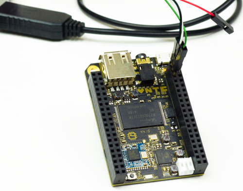
SSH
SSH (or “Secure Shell”) is a common way to control a computer remotely over a network. You’ll need to first get your computer’s network name or IP address before you can connect.
Connect to CHIP over a network
CHIP comes with avahi installed, meaning you can simply refer to it with a name, rather than an IP address
ssh chip@chip.local
In some situations, you’ll need to use CHIP’s IP address to connect, in which case the command would look like:
ssh chip@10.1.1.99
You’ll be asked for CHIP’s password. The default password is chip.
This process is the same if CHIP is connected to the network using built-in wireless or a USB-Ethernet adapter.
How to get your IP address
The easiest way to get CHIPs IP address is to hook up a monitor and keyboard. Bootup, log in, connect to the network if you need to, and use the command
hostname -i
which results in your IP address, which might look like this:
10.1.1.99
If the hostname -i command doesn’t work you can use
ip addr show dev wlan0
(You can use the abbreviated ip a for an easy to remember command).
which will output a lot of data. Look for the line wlan0 and the entry inet, something like:
inet 10.1.1.99
Make Connections To CHIP Easy
You may want to setup your network so it will always provide the same (static) IP address to CHIP. You can then rely on CHIP always having the same IP address.
Alternatively, you can setup zero configuration networking to give your CHIP an easily remembered name.
You are now free to do whatever it is you do with Linux command line on CHIP.
Control CHIP Using a Serial Terminal
Once you’ve connected CHIP to your computer with the UART or USB cable, open up a terminal. There’s lots out there. Here’s a few:
No matter the software, you’ll need to set some settings for the port (aka connection). You’ll probably only need to set the baud rate, as the others will be defaults:
- Baud Rate (Data Rate): 115200
- Data Bits: 8
- Parity: none
- Stop bits: 1
- Flow control: none
Using screen
If you are using screen, the command will look something like this:
screen /dev/tty.usbserial 115200 # on macOS
screen /dev/ttyUSB0 115200 # on linux
Here’s a clever way that work on any system to just connect to the most recent serial device you plugged in:
screen $(ls -tw 1 /dev/tty* | head -1) 115200
What comes after the ’/dev/’ may vary among different systems and connections. You can narrow down the choices by using one of the commands
ls /dev/tty* # everything
ls -t /dev/tty* | head -5 # the five most recent
to list the serial devices.
Now power up CHIP. You could do this at anytime, but you’ll have the most reliable experience powering CHIP after connecting the USB-UART wires. If you make the serial connection after booting chip, you’ll probably need to hit 'return’ on your keyboard a few times to get CHIP to send some data to you and print in your terminal.
You’ll then be prompted for login. Defaults are username chip and password chip.
You are now free to do whatever it is you do with Linux command line on CHIP.
Using PuTTy
If you are on Windows using PuTTy, you’ll probably want to open the windows Device Manager to get the COM name for the serial port. The device won’t show up in the Ports list until after the kernel loads and presents the device, so it may take a minute or so before Windows actually detects it.
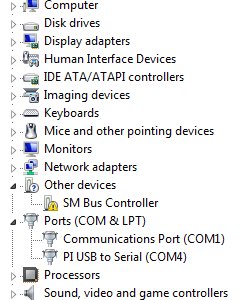
In the PuTTy configuration panel, you can now use the COM name to set it up. In this case, it’s “COM4”:
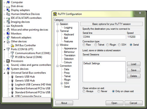
Press “Open” to open a terminal window ,where you can log in to CHIP with username and password chip.
You are now free to do whatever it is you do with Linux command line on CHIP.
Zero Configuration Networking
You can make working with CHIP on a local network much more convenient by installing zero-conf networking. OS X users may know this as “Bonjour”.
With zero-conf properly configured, your CHIP can be contacted using a name, such as chip.local, rather than an IP. This is especially convenient, if you are moving CHIP to different networks that might assign different IP addresses. The key technology for this in Linux is the avahi set of tools. There are a few related packages, but this tutorial is a minimal installation to get it up and running.
Requirements
- CHIP
- SSH or serial connection to CHIP or
- Monitor and keyboard
- Connection to a network
Install avahi
Getting avahi running is extremely simple. First, install the avahi-daemon:
sudo apt-get install avahi-daemon
to install the necessary libraries. You may want to configure the daemon with this service file so you can find Apple Bonjour devices from CHIP :
sudo nano /etc/avahi/services/afpd.service
Then just copy and paste this XML into it:
<?xml version="1.0" standalone='no'?><!--*-nxml-*-->
<!DOCTYPE service-group SYSTEM "avahi-service.dtd">
<service-group>
<name replace-wildcards="yes">%h</name>
<service>
<type>_afpovertcp._tcp</type>
<port>548</port>
</service>
</service-group>
Then restart avahi-daemon:
sudo /etc/init.d/avahi-daemon restart
You can now find the hostname that you can use to reach CHIP:
hostname
which will probably return “chip” as the hostname.
Use Zero-Conf
From a terminal on another computer you can try accessing CHIP with the network name chip.local
ssh chip@chip.local
and enter the password (default is chip). That’s it. You can now reach CHIP without knowing the IP.
Change the hostname
If you have more than one CHIP on the network, or you just want to change the name from “chip” to fit into your network name scheme, you can modify the hostnames file. Open the file in an editor:
sudo nano /etc/hostname
where you’ll see a single word “chip.” Just modify that line (for example, change it to “bobofettywap”) and save the file.
You’ll also need to modify the hosts file where you’ll need to change the first line 127.0.0.1 chip where you replace “chip” with your new hostname.
sudo nano /etc/hosts
Finally, to get this new name to broadcast over the network restart avahi-daemon:
sudo /etc/init.d/avahi-daemon restart
You can now access chip with the new name:
ssh chip@bobofettywap.local
Other packages
You may want to explore some of the other features of avahi, such as browsing a network for other zero-configure enabled computers. There’s a package you can install:
  sudo apt-get update &
  sudo apt-get install avahi-utils
which gives you a set of tools for browsing the network, such as the command
avahi-browse -d local _ssh._tcp --resolve -t
which will list other zero-configure-enabled devices on the local network. You could ssh to your Macintosh named “bananna”, for example with
ssh username@bananna
An alternative to just installing the avahi-daemon, you can
sudo apt-get install libnss-mdns
which installs some other tools for network name propagation.
Troubleshooting SSH with avahi
If your computer returns the error
ssh: Could not resolve hostname chip.local: nodename nor servname provided, or not known
then you either need to wait a minute or try installing avahi-daemon again, but pay closer attention to any errors that apt-get returns.
If you can’t connect to CHIP even though you are sure avahi is properly configured, confirm that your CHIP and the computer you are trying to connect are on the same local network (and on the same subnet).
FAQs
Frequently Asked Questions
Do I need to install something for CHIP to be a computer?
No. CHIP comes preinstalled with the CHIP Operating System and several applications. Just power on, and get started.
Why composite video?
Several reasons:
- Televisions are the most commonly available screen in the world and the vast majority of them have a composite input.
- Composite video can be integrated without adding licensing fees to the cost of C.H.I.P.
- Composite is a very low profile connector, allowing us to keep the footprint of the board small for people wanting to build C.H.I.P. into projects.
Is CHIP an exposed circuit board?
Yes! Not having a case for C.H.I.P. is one of the ways we are able to keep our costs down. As makers, we’re excited to introduce people to the physical components of computers and show them that electronics aren’t scary, they’re fun! We hope to spark curiosity and encourage people to begin tinkering themselves.
What resolution can CHIP function at?
With the VGA and HDMI adapters, C.H.I.P. is designed to work at 720p resolution, though the Mali 400 GPU is technically capable of up to 1080p outputs. The composite video connector operates at the “SD” resolution of 640x480.
How is CHIP so cheap?
QUANTITY. Our partners at Allwinner worked hard to help us find how to reduce costs, so we could introduce C.H.I.P. to EVERYBODY. To sell C.H.I.P. for $9, we need to order tens of thousands of chips. By using common, available, and volume-produced processor, memory, and wifi chips, we are able to leverage the scales at which tablet manufacturers operate to get everyone the best price.
What does CHIP stand for?
We’re curious to hear what you think ;)
Is CHIP open source? Where are the docs?
YES! Very open source! We are still in the process of testing and refining the whole C.H.I.P. family. As we hit design completion, we’ll release our design files. We’ve already released quite a bit! Check them out at our GitHub repo!
Can I upgrade CHIP’s RAM/Storage/Processor?
Technically, yes, but the components are soldered on and not intended to be swapped out. If you really like reworking small BGA and fine pitch components, though, we won’t stop you. :)
If you want additional storage, you can attach a USB drive!
How many accessible pins does CHIP have?
Eight digital GPIOs, one PWM pin, SPI, TWI (I2C), UART, USB, CSI, Parallel LCD output, touchpanel input, stereo audio out, mono audio in, composite video out, and a whole bunch of power rails in and out.
The most up-to-date information is on our GitHub repo.
Can I make my own adapter board?
Absolutely! The schematics and layout for the boards, both of C.H.I.P. and C.H.I.P.’s adapters will be released as they are finalized for production. From that, you can build whatever sort of adapters or add-ons you want!
Does the HDMI adapter have HDMI audio output?
Not at this time. Because there is no onboard digital audio support from our processor, C.H.I.P.’s current design only has analog audio output via the ⅛” headphone/composite jack. Adding a USB sound card is the easiest way to beef up your CHIP’s digital audio output options.
Does Linux come pre-installed?
YES! C.H.I.P. comes with Linux installed, and a selection of our favorite programs and games. Like any real computer, you can download more software and customize C.H.I.P.s applications and operating system to suit your needs!
Can I plug in a Keyboard, Mouse, AND Power?
The easiest way to accomplish this is to power C.H.I.P. as usual via the microUSB port. Attach a USB keyboard with an accessory USB port on it, then connect your wired mouse to that port. Alternatively, a bluetooth keyboard or mouse can be used to free up the need for USB connections.
For more advanced use cases, C.H.I.P. can be powered via its interconnects, leaving both the full size USB and microUSB ports available to attach devices to.
Can I stream Netflix?
Due to a lack of support for Silverlight (the back-end software that allows Netflix to be streamed) in Linux, it is unlikely that Netflix will work on C.H.I.P. using entirely open-source software. This would require someone to come up with an alternate back-end. That said, some very astute backers have reported that Netflix should be possible by installing the Google Chrome browser, which allows Netflix streaming via HTML5.
Does CHIP have a power switch?
Yes! C.H.I.P. has a tiny power on-off button and a status LED on the board itself.
Can I make a supercomputer by linking 100 CHIPs together?
We’re focused on individual uses of C.H.I.P. but what you’re talking about is called clustering, and may be possible – A good place to start, if you’re interested in clustering, is reading up on Debian-Beowulf
What about a camera?
C.H.I.P. has exposed CSI pins on its headers for integrating a camera directly to the processor, or if drivers and sensor tuning sound like a bit much, you can always add a USB camera too.
How do I connect a display?
You can connect a display through the 3.5mm (⅛”) TRRS composite video port on C.H.I.P. If you’d like to connect to a vga or hdmi monitor, we have adapters available for that! You can also connect any parallel LCD to the exposed display pins on C.H.I.P.’s headers.
Does CHIP have an SD card slot?
No. But by integrating reliable storage onto the device, we’re able to both save you a “getting started” cost and allow Linux to come preinstalled on C.H.I.P. meaning it’s ready to go when it arrives at your door. One of the big goals of this project is making C.H.I.P. easy to use, and this goes a long way towards that end. If you need additional storage, it’s easy to add an SD card reader or other USB storage with the built-in USB port.
Can I connect to composite video AND audio out at the same time?
YES! The 1/8" mini (TRRS) jack can be used either with a video-only cable, audio only cable, headphones, headphones with mic, OR a combined Audio/Video composite cable. Pretty versatile little port, isn’t it!?
What software does CHIP ship with? What programs can it run?
C.H.I.P. comes pre-loaded with some of our favorite open-source applications, and the ability to install hundreds more. What’s even more exciting, though, is that if any given program isn’t supported out of the box, the community can work together to make it happen. That’s what we <3 about Open Source Software.
What programming languages does CHIP support?
C.H.I.P. is a real computer, and can run software written in all kinds of programming languages, so long as there’s a compiler for them. Python, Java (via JDK8), Ruby, PHP, Squeak, C++, JS, Assembly, BF.. even our favorite, ArnoldC, and lots lots more.
Does CHIP have Real Time Clock?
No, but adding an RTC is a great (and easy) hardware hack, for the folks that need it. For most people, though, an RTC isn’t necessary since it is easy to get C.H.I.P. to pull time from a remote NTP server over wifi.
What voltage are GPIOs?
CHIP uses 3V3 digital logic on GPIOs.
What connector is used on the battery?
We are using a JST-2.0 PH 2-pin shrouded male connector to connect LiPo cells to C.H.I.P. In the current design there are also BATT pins available on the interconnect headers, which allow alternate battery connectors/placements when attaching C.H.I.P. to a custom PCBA.
I want to know more about the Allwinner R8 processor!
You can find out more from the Allwinner R8 User Manual and the R8 Datasheet
What kind of battery can I use with CHIP?
Any single-cell (3.7V) LiPo battery will work with C.H.I.P. You can go bigger or smaller than 3000mAH as needed for your project!
Does CHIP’s WiFi support AP mode?
YES!
Does C.H.I.P. have an ethernet port?
No. But it does have built-in 802.11b/g/n wifi. But if you like wires, you can use a USB-Ethernet connector.
Is there a command that lets me know more about the CPU and Memory?
It’s a computer! It will tell you anything. If you want to find out more details about CHIP’s processor, use the command:
cat /proc/cpuinfo
This will give output similar to:
processor   : 0
model name  : ARMv7 Processor rev 2 (v7l)
BogoMIPS    : 1001.88
Features    : half thumb fastmult vfp edsp neon vfpv3 tls vfpd32
CPU implementer : 0x41
CPU architecture: 7
CPU variant : 0x3
CPU part    : 0xc08
CPU revision    : 2

Hardware    : Allwinner sun4i/sun5i Families
Revision    : 0000
Serial      : 162542c10c427777
If you want know more about the memory:
cat /proc/meminfo
with output something like:
MemTotal:         507108 kB
MemFree:          298600 kB
MemAvailable:     382592 kB
Buffers:               0 kB
Cached:            92216 kB
SwapCached:            0 kB
Active:            98752 kB
Inactive:          64096 kB
Active(anon):      73180 kB
Inactive(anon):     5812 kB
Active(file):      25572 kB
Inactive(file):    58284 kB
Unevictable:           0 kB
Mlocked:               0 kB
HighTotal:             0 kB
HighFree:              0 kB
LowTotal:         507108 kB
LowFree:          298600 kB
SwapTotal:             0 kB
SwapFree:              0 kB
Dirty:                 0 kB
Writeback:             0 kB
AnonPages:         70660 kB
Mapped:            37768 kB
Shmem:              8360 kB
Slab:              22784 kB
SReclaimable:      11560 kB
SUnreclaim:        11224 kB
KernelStack:        1176 kB
PageTables:         2240 kB
NFS_Unstable:          0 kB
Bounce:                0 kB
WritebackTmp:          0 kB
CommitLimit:      253552 kB
Committed_AS:     615216 kB
VmallocTotal:     507904 kB
VmallocUsed:       14560 kB
VmallocChunk:     482532 kB
Troubleshooting FAQ
CHIP Won’t Boot or Startup
Problem: I attached a keyboard, monitor, and powered CHIP, but it does not do anything. The LEDs are on, but I can’t do anything with CHIP!
Fixes: Don’t worry, your CHIP is probably fine. This can be fixed by reflashing CHIP from our web flasher.
- Follow the instructions for flashing your CHIP.
Sudden Shutdown (Brown-out)
Problem: I attached a mouse and keyboard, and my CHIP suddenly turned off.
Fixes: Like most tiny computers, the USB port on CHIP provides a limited amount of power. When you plug in a keyboard and an optical mouse, for example, they will draw too much current from CHIP, not leaving enough for the processor. As a result, CHIP will immediately shut down. There are a few ways to avoid this.
- Use a powered USB hub
- Use a bluetooth keyboard and mouse. Yes, this is a very specific solution, but a good one when you are only using the USB port for keyboard and mouse. Keeps your desk cleaner too!
- Execute the command
sudo axp209 --no-limitin the terminal before you attach your USB peripherals. - Provide power from a supply connecting ground and 5V the pins headers 1 and 2 on U13.
Problem: My CHIP booted fine until it got to loading the desktop GUI, then it shut down.
Fixes: This is usually the result of an underpowered power supply. We recommend a 5V power supply with a minimum 1A current rating.
- You can find the current rating on your power supply’s “Output” - it should read 1000 mA or 1A (or a higher number). You may need a magnifying glass to read it, but they all should have this info on the label!
- Instead of powering CHIP using the microUSB port, try using the header pins CHG-IN (U13-2) and GND (U13-1).
- Add a LiPo battery. This provides enough extra current and power buffer to prevent this problem.
No Video Output
Problem: Monitor is attached, but there is no video on my monitor
Fixes: There are a few possible problems here
- wrong TRRS arrangement: try different ends of your cable. Make sure is subscribes to this use of the tip, rings, and sleeve
- PAL monitor: CHIP outputs NTSC format video by default. You can change this, however, by following this guide.
- Video trace cut for mic in: This is pretty unlikely, but if you are working with a used CHIP, it may be that the tip connector has been switched to work as a microphone input. Before you do fix this with a bit of solder, take a close look at your board to see if there is evidence of a score mark indicating the cut trace.
How to Contact Us
If you need more support, try our forums or email us.
Compliance Statement
FCC ID: 2AF9F-HELLA1337
IC: 20863-HELLA1337
FCC
This device complies with part 15 of the FCC Rules. Operation is subject to the following two conditions: (1) This device may not cause harmful interference, and (2) this device must accept any interference received, including interference that may cause undesired operation.
Industry Canada
This device complies with Industry Canada license-exempt RSS standard(s). Operation is subject to the following two conditions:
- This device may not cause harmful interference;
- This device must accept any interference received, including interference that may cause undesired operation of the device.
Cet appareil est conforme à Industrie Canada une licence standard RSS exonérés (s). Son fonctionnement est soumis aux deux conditions suivantes: 1. Cet appareil ne doit pas provoquer d'interférences 2. Cet appareil doit accepter toute interférence reçue, y compris les interférences pouvant provoquer un fonctionnement indésirable de l'appareil.
Information to User
CAUTION: Changes or modifications not expressly approved for compliance could void your authority to operate this equipment.